10 2.10 Compare SAW and ESW. (a) Which one has a higher heat efficiency? (b) Explain why.
11 2.11 Compare GMAW and flux‐cored arc welding (FCAW) under the same power input, travel speed, and filler wire deposition rate. Which weld cool down more slowly, and why?
This chapter deals with fluid flow in the arc and the weld pool. It draws heavily on the work at UW‐Madison on computer simulation of weld‐pool convection, flow visualization, weld‐pool surface deformation and oscillation, ripple formation on the weld surface, and how these are affected by the surface‐active agent. The chapter also discusses the recent work on: (i) the metal−vapor effect on fluid flow in the arc, and (ii) fluid flow in the nugget in resistance spot welding (RSW).
As shown previously in Figure 2.11, in gas−tungsten arc welding (GTAW) the tip angle of the tungsten electrode has a significant effect on the shape of the arc. The arc tends to become more constricted as the electrode tip changes from sharp to blunt. The change in the shape of the electrode tip changes fluid flow and heat transfer in the arc, which in turn changes the shape of the arc.
Figure 3.1shows the body‐fitting coordinate system used in the early work of Tsai and Kou [1] on computer simulation of fluid flow and heat transfer in a gas‐tungsten welding arc. Fluid flow and heat transfer in GTAW has been studied by computer simulation [1–6]. An example is the work by Tsai and Kou [1], which demonstrated the significant effect of the electrode tip geometry on the arc. Although the work did not consider the metal vapor in the arc and the pool surface shape as in the more recent work, it is simple and thus useful for explaining basic fluid flow in the arc before discussing more complicated details.
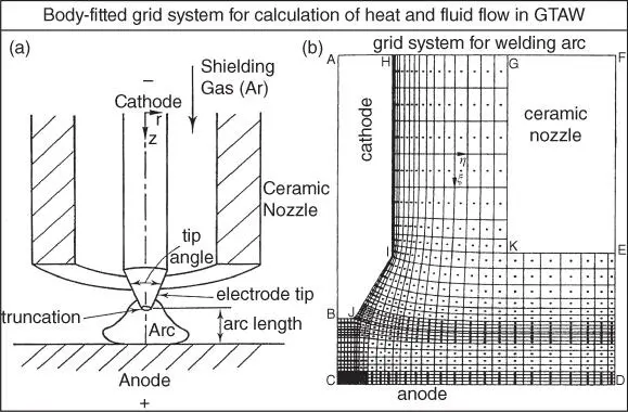
Figure 3.1Gas‐tungsten welding arc: (a) sketch; (b) body‐fitted grid system for calculation of heat transfer and fluid flow.
Source : Tsai and Kou [1]. © Elsevier.
Figure 3.2is a schematic sketch of an arc produced by a tungsten electrode with a sharp tip that is truncated. The polarity is DC electrode negative. The electric current converges from the larger workpiece to the smaller electrode tip. It tends to be perpendicular to the electrode tip surface and the workpiece surface (flat), as illustrated in Figure 3.2a. The electric current induces a magnetic field, which is out of the plane of the page (as indicated by the front view of an arrow) on the left and into the page (as indicated by the rear view of an arrow) on the right. The magnetic field and the converging electric‐current field together produce a downward and inward Lorentz force Fto push the ionic gas along the conical surface of the electrode tip. The downward momentum is strong enough to cause the high‐temperature ionic gas to impinge on the workpiece surface and turn outward along the workpiece surface, thus producing a bell‐shaped arc, as illustrated in Figure 3.2b.
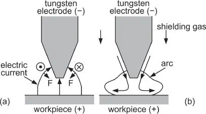
Figure 3.2Arc produced by a tungsten electrode with a sharp tip: (a) Lorentz force (F); (b) fluid flow. The directions of Lorentz force and fluid flow shown for DCEN here remain the same for DCEP because the electric current and the magnetic filed it induces are both reversed in direction.
Figure 3.3(left) shows the current density distribution in a 2 mm long, 200 A arc produced by a 3.2 mm diameter electrode with a 60° angle tip. The electric current near the electrode tip is essentially perpendicular to the surface. The Lorentz force, shown in Figure 3.3(right), is downward and inward along the conical surface of the electrode tip. As shown in Figure 3.4, this force produces a high velocity jet of more than 200 m/s maximum velocity and the jet is deflected radially outward along the workpiece surface. This deflection of the high‐temperature jet causes the isotherms to push outward along the workpiece surface, thus resulting in a bell‐shaped arc.
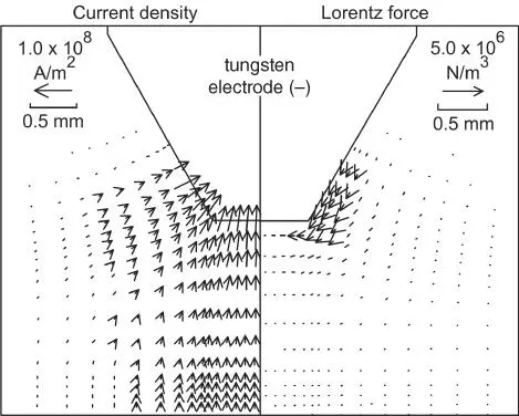
Figure 3.3Current‐density field (left) and Lorentz force (right) in an arc produced by a tungsten electrode with a 60° tip angle.
Source : Tsai and Kou [1]. © Elsevier.
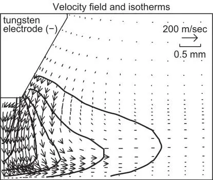
Figure 3.4Velocity and temperature fields in an arc produced by a tungsten electrode with a 60° tip angle. The isotherms from right to left are 11 000, 13 000, 15 000, 17 000, 19 000, and 21 000 K.
Source : Tsai and Kou [1]. © Elsevier.
With a flat‐end electrode, on the other hand, there is no longer a sharp electrode tip to act as a fixed cathode spot, where the electric current enters the electrode. Consequently, the cathode spot moves around rather randomly and quickly in the flat electrode end. The time‐averaged diameter of the area covered by the moving spot can be considered as the effective cathode spot size. Without a conical surface at the electrode end, the resultant Lorentz force is still inward and downward, but the downward component is reduced as illustrated in Figure 3.5a. Consequently, the resultant arc can be expected to be more constricted, as shown in Figure 3.5b.
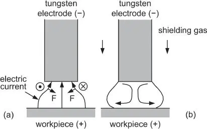
Figure 3.5Arc produced by a tungsten electrode with a flat end: (a) Lorentz force (F); (b) fluid flow.
Figure 3.6(left) shows the current density distribution in a 2 mm long, 200 A arc produced by a 3.2 mm diameter electrode with a flat end and a 2.4 mm‐diameter cathode spot. The Lorentz force, shown in Figure 3.6(right), is less downward pointing than that in the case of a 60°‐angle electrode ( Figure 3.3). As shown in Figure 3.7, the isotherms are not pushed outward as much, and the resultant arc is thus more constricted.
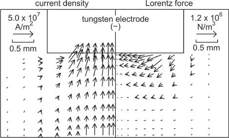
Figure 3.6Current‐density field (left) and Lorentz force (right) in an arc produced by a tungsten electrode with a flat end.
Source : Tsai and Kou [1]. © Elsevier.
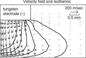
Figure 3.7Velocity and temperature fields in an arc produced by a tungsten electrode with a flat end. The isotherms from right to left are 11 000, 13 000, 15 000, 17 000, 19 000 and 21 000 K.
Source : Modified from Tsai and Kou [1]. © Elsevier.
3.2 Effect of Metal Vapor on Arcs
3.2.1 Gas−Tungsten Arc Welding
Tanaka et al. [7] showed that Fe vapor can significantly increase the electrical conductivity of the welding arc. As can be expected, the electrical conductivity of He is lower than that of Ar because He has a significantly higher ionization energy than Ar (Table 1.2). That is, He is more difficult to dissociate into electrons and positive ions to help conduct the welding current as explained in Chapter 1. Figure 3.8shows that He has lower conductivity than Ar, and also shows that the Fe vapor can significantly increase the electrical conductivity of both Ar and He at lower temperatures. The distributions of temperature and Fe vapor were calculated for stationary arcs over 304 stainless steel at 150 A current and 5 mm arc length. They showed significantly more Fe vapor in the He arc than the Ar arc. After welding for 20 seconds, much Fe vapor deposit appeared around the He weld but little around the Ar weld, as shown in Figure 3.9. Without considering the Fe vapor, the calculated current density at the pool surface is too high and the calculated weld too deep.
Читать дальше
