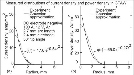
Figure 3.13Gas–tungsten welding arc: (a) power‐density distribution; (b) current‐density distribution.
Source : From Lu and Kou [17]. Welding Journal, February 1988, © American Welding Society.
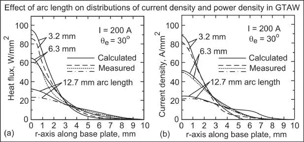
Figure 3.14Effect of arc length on gas‐tungsten welding arcs: (a) power‐density distributions; (b) current‐density distributions.
Source : Lee and Na [6]. Welding Journal, September 1996, © American Welding Society.
The power‐ and current‐density distributions measured by the split‐anode method ( Figures 3.13and 3.14) do not show the effect of metal vapor in the arc. The vapor can flatten the distributions, because it can increase the electrical conductivity of the cooler outer portion of the arc (Figure 3.8), and hence reduce the weld depth.
3.4 Fluid Flow in Weld Pools
3.4.1 Driving Forces for Fluid Flow
The driving forces for fluid flow in the weld pool include the buoyancy force, the Lorentz force, the shear stress induced by the surface tension gradient at the weld pool surface ,and the shear stress acting on the pool surface by the arc plasma. The arc pressure is another force acting on the pool surface but its effect on fluid flow is small especially below 200 A [18, 19], which is usually the case for GTAW. The driving forces for fluid flow in the weld pool, shown in Figure 3.15, are explained as follows:
Buoyancy force. The density of the liquid metal (ρ) decreases with increasing temperature (T). Because of the heat source is located above the center of the pool surface, the liquid metal is warmer at point a and cooler at point b. Point b is near the pool boundary, where the temperature is lowest at the melting point. As shown in Figure 3.15a, gravity causes the heavier liquid metal at point b to sink. Consequently, the liquid metal falls along the pool boundary and rises along the pool axis and, as shown in Figure 3.15b.
Lorentz force. GTAW with DC electrode negative is used as an example for the purpose of discussion. The electric current in the workpiece converges toward the tungsten electrode (not shown) and hence near the center of the pool surface. This converging current field, together with the magnetic field it induces, causes a downward and inward Lorentz force, as shown in Figure 3.15c. As such, the liquid metal is pushed downward along the pool axis and rises along the pool boundary, as shown in Figure 3.15d. The area on the pool surface where the electric current goes through is called the anode spot (πb2 where b is the effective radius of the current‐density distribution). The smaller the anode spot is, the more the current field converges from the workpiece (through the weld pool) to the anode spot, and hence the greater the Lorentz force becomes to push the liquid metal downward.
Shear stress induced by surface tension gradient. In the absence of a surface‐active agent, the surface tension (γ) of the liquid metal decreases with increasing temperature (T), namely, ∂γ/∂T < 0. As shown in Figure 3.15e, the warmer liquid metal with a lower surface tension at point a is pulled outward by the cooler liquid metal with a higher surface tension at point b. In other words, an outward shear stress is induced at the pool surface by the surface tension gradient along the pool surface. This causes the liquid metal to flow from the center of the pool surface to the edge and return below the pool surface, as shown in Figure 3.15f. Surface‐tension‐driven convection is also called thermocapillary convection or Marangoni convection.
Shear stress induced by plasma jet. As can be seen in Figure 3.4, the arc plasma can be expected to move outward at high speeds along the pool surface, thus exerting an outward shear stress at the pool surface as illustrated in Figure 3.15g. This shear stress causes the liquid metal to flow from the center of the pool surface to the pool edge and return below the pool surface, as shown in Figure 3.15h. Matsuwana et al. [20] showed that the effect of the shear stress can be significant when the arc is very long, e.g. 8 mm.
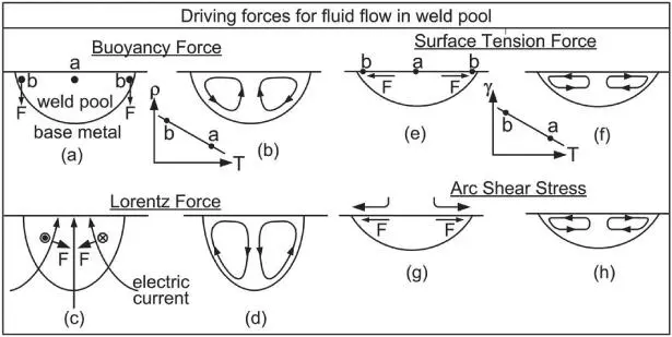
Figure 3.15Driving forces for weld pool convection: (a, b) buoyancy force; (c, d) Lorentz force; (e, f) shear stress caused by surface tension gradient; (g, h) shear stress caused by arc plasma.
These driving forces are included either in the governing equations or as boundary conditions in the computer modeling of fluid flow in the weld pool [21]. Oreper et al. [22] developed the first 2D model for heat transfer and fluid flow in a stationary arc weld pool, but the pool shape was assumed (not calculated). Kou and Sun [23] developed the first 2D axisymmetric (r, z) model of heat transfer and fluid flow that calculated the unknown shape of the stationary arc weld pool. Kou and Wang [24–26] subsequently developed the first 3D (x, y, z) model of heat transfer and fluid flow for moving arc and laser weld pools. Calculating the weld pool shape is essential because the effect of fluid‐flow driving forces on the weld pool shape can be demonstrated clearly. Numerous computer models for fluid flow in the weld pool have been developed by subsequent investigators.
3.4.2 Heiple's Theory for Weld Pool Convection
Heiple et al. [27–31] proposed that, when a surface‐active agent is present in the liquid metal in a small but significant quantity, ∂γ/∂T can be changed from negative to positive, thus reversing the direction of Marangoni convection and making the weld pool much deeper. Heiple's theory is illustrated in Figure 3.16[32]. Examples of surface‐active agents in steel and stainless steel are S, O, Se, and Te. Keene et al. [33] showed ∂γ/∂T of liquid stainless steel can be reversed if the S is increased to, e.g. 160 ppm (Figure 3.16a).
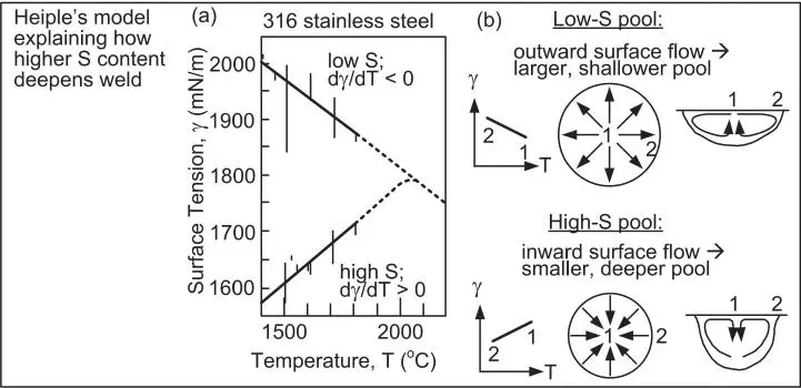
Figure 3.16Effect of sulfur on surface tension and weld penetration: (a) surface tension data; (b) model of Heiple and Roper.
Source : Kou, Limmaneevitchitr, Wei [32]. Welding Journal, December 2011, © American Welding Society.
Since surface tension is a pulling force, when surface‐tension gradients exist along the weld pool surface, the liquid of higher surface tension pulls the liquid of lower surface tension toward itself. This causes the liquid on the weld pool surface to flow from the location of lower surface tension to that of higher surface tension.
Heiple's theory is explained in Figure 3.16b. In the absence of a surface‐active agent, the warmer liquid metal of lower surface tension near the center of the pool surface is pulled outward by the cooler liquid metal of higher surface tension at the pool edge. In the presence of a surface‐active agent, on the other hand, the cooler liquid metal of lower surface tension at the edge of the pool surface is pulled inward by the warmer liquid metal of higher surface tension near the center of the pool surface, where it is heated by the heat source before going axially downward to the pool bottom. This increases melting at the bottom of the pool, thus increasing the weld penetration.
Figure 3.17shows two YAG laser welds made in 6.4‐mm‐thick 304 stainless steel plates in the conduction mode at 3000 W power and 3.39 mm/s travel speed [34]. The weld in the plate with 140 ppm S is deeper than that with 40 ppm S, consistent with Heiple's theory.
Читать дальше
