Source : Mendez and Eagar [2]. © ASM.
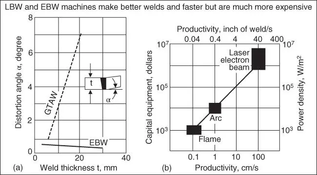
Figure 1.4Comparisons between welding processes: (a) angular distortion; (b) capital equipment cost.
Source : Mendez and Eagar [2]. © ASM.
1.1.1.2 Welding Processes and Materials
Table 1.1summarizes the fusion welding processes recommended for carbon steels, low‐alloy steels, stainless steels, cast irons, nickel‐base alloys, and aluminum alloys [3]. For one example, GMAW can be used for all the materials of almost all thickness ranges while GTAW is mostly for thinner workpieces. For another example, arc welding processes that require the use of a flux, such as SMAW, SAW, FCAW, and ESW, is not used for aluminum alloys.
Table 1.1Overview of welding processes. Source: Welding Handbook [3], vol 1, 7th edition, © American Welding Society.
|
|
Joining process a |
| Material |
Thickness b |
SMAW |
SAW |
GMAW |
FCAW |
GTAW |
PAW |
ESW |
OFW |
EBW |
LBW |
| Carbon steels |
S |
x |
x |
x |
|
x |
|
|
x |
x |
x |
| I |
x |
x |
x |
x |
x |
|
|
x |
x |
x |
| M |
x |
x |
x |
x |
|
|
|
x |
x |
x |
| T |
x |
x |
x |
x |
|
|
x |
x |
x |
|
| Low‐alloy steels |
S |
x |
x |
x |
|
x |
|
|
x |
x |
x |
| I |
x |
x |
x |
x |
x |
|
|
|
x |
x |
| M |
x |
x |
x |
x |
|
|
|
|
x |
x |
| T |
x |
x |
x |
x |
|
|
x |
|
x |
|
| Stainless steels |
S |
x |
x |
x |
|
x |
x |
|
x |
x |
x |
| I |
x |
x |
x |
x |
x |
x |
|
|
x |
x |
| M |
x |
x |
x |
x |
|
x |
|
|
x |
x |
| T |
x |
x |
x |
x |
|
|
x |
|
x |
|
| Cast iron |
I |
x |
|
|
|
|
|
|
x |
|
|
| M |
x |
x |
x |
x |
|
|
|
x |
|
|
| T |
x |
x |
x |
x |
|
|
|
x |
|
|
| Nickel and alloys |
S |
x |
|
x |
|
x |
x |
|
x |
x |
x |
| I |
x |
x |
x |
|
x |
x |
|
|
x |
x |
| M |
x |
x |
x |
|
|
x |
|
|
x |
x |
| T |
x |
|
x |
|
|
|
x |
|
x |
|
| Aluminum and alloys |
S |
|
|
x |
|
x |
x |
|
x |
x |
x |
| I |
|
|
x |
|
x |
|
|
|
x |
x |
| M |
|
|
x |
|
x |
|
|
|
x |
|
| T |
|
|
x |
|
|
|
|
|
x |
|
a)Process code: SMAW, shielded metal arc welding; SAW, submerged arc welding; GMAW, gas−metal arc welding; FCAW, flux cored arc welding; GTAW, gas–tungsten arc welding; PAW, plasma arc welding; ESW, electroslag welding; OFW, oxyfuel gas welding; EBW, electron beam welding; LBW, laser beam welding.
b)Thickness: S, sheet, up to 3 mm (1/8 in.); I, intermediate, 3−6 mm (1/8−¼ in.); M, medium, 6−19 mm (¼−¾ in.); T, thick, 19 mm (¾ in. and up); X, recommended.
1.1.1.3 Types of Joints and Welding Positions
Figure 1.5shows the basic weld joint designs in fusion welding: the butt, lap, T‐, edge, and corner joints. Figure 1.6shows the transverse cross sections of some typical weld joint variations. The surface of the weld is called the face, the two junctions between the face and the workpiece surface are called the toes, and the portion of the weld beyond the workpiece surface is called the reinforcement. Figure 1.7shows four basic welding positions.

Figure 1.5Five basic types of weld joint designs.
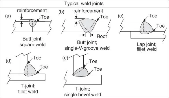
Figure 1.6Typical weld joint variations.

Figure 1.7Four welding positions.
1.1.2 Solid‐State Welding Processes
In addition to fusion welding processes, various solid‐state welding processes have also been developed. Some of them are shown as follows:
1 (a) Friction Stir Welding:Friction stir welding (FSW)Friction stir spot welding (FSSW)
2 (b) Friction Welding:Linear friction welding (LFW)Rotary friction welding (RFW)
3 (c) Fast‐Collision Welding:Explosion welding (EXW)Magnetic pulse welding (MPW)
4 (d) Diffusion Welding
1.2 Gas Welding
1.2.1 The Process
Gas welding is a welding process that melts and joins metals by heating them with a flame caused by the reaction between a fuel gas and oxygen. Oxyacetylene welding (OAW), shown in Figure 1.8, is the most commonly used gas welding process because of its high flame temperature. A flux may be used to deoxidize and cleanse the weld metal. The flux melts, solidifies, and forms a slag skin on the resultant weld metal. Figure 1.9shows three different types of flames in OAW: neutral, reducing, and oxidizing [4], which are described next.
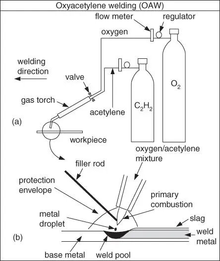
Figure 1.8Oxyacetylene welding: (a) overall process; (b) welding area enlarged.
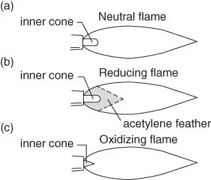
Figure 1.9Three types of flames in oxyacetylene welding [4].
Source : Welding Journal, 1969, © American Welding Society.
1.2.2 Three Types of Flames
1.2.2.1 Neutral Flame
This refers to the case where oxygen (O 2) and acetylene (C 2H 2) are mixed in equal amounts and burned at the tip of the welding torch. A short inner cone and a longer outer envelope characterize a neutral flame ( Figure 1.9a). The inner cone is the area where the primary combustion takes place through the chemical reaction between O 2and C 2H 2, as shown in Figure 1.10. The heat of this reaction accounts for about two‐thirds of the total heat generated. The products of the primary combustion, CO and H 2, react with O 2from the surrounding air to form CO 2and H 2O. This is the secondary combustion, which accounts for about one‐third of the total heat generated. The area where this secondary combustion takes place is called the outer envelope. It is also called the protection envelope since CO and H 2here consume the O 2entering from the surrounding air, thereby protecting the weld metal from oxidation. For most metals, a neutral flame is used.
Читать дальше
