1 ...8 9 10 12 13 14 ...38 Part III, The Partially Melted Zone, also discusses more on the new progress made at UW‐Madison, including liquation (liquid formation) and liquation‐induced cracking. A simple criterion is proposed to predict how filler metals can be selected in arc welding to eliminate liquation cracking. Evidence of liquation and liquation cracking in friction stir welding (FSW) is presented. In Al‐to‐Mg butt and lap FSW, the interesting and significant effect of the position of Al relative to Mg on the joint strength is explained. Interestingly, liquid droplets have been shown even though FSW is considered as solid‐state welding.
Part IV, The Heat‐Affected Zone (HAZ), has been reorganized into the following new chapters: Chapters 17, 18, 19, and 20.
Part V, Special Topics, is a new chapter. It has been added to introduce some topics of high current interest, such as Chapters 21– 24. Chapters 23and 24, and several sections in Chapter 22discuss heavily on the new progress at UW‐Madison.
The author thanks God for giving him the opportunity and ability to do what he has done in welding metallurgy. He applied his training in transport phenomena (BS in Chemical Engineering at the National Taiwan University) and solidification (PhD in Metallurgy at the Massachusetts Institute of Technology under Professor Merton C. Flemings) to welding. His work was supported by funding from the National Science Foundation (NSF), NASA, the University of Wisconsin Foundation, the AWS Foundation, Hobart Brothers, General Motors, ALCOA, Howmet, CompuTherm, and other companies, which are greatly appreciated. The NSF support includes solidification cracking and ductility‐dip cracking in stainless steel welds under grant number DMR1904503, solidification cracking of Al alloys under grant number DMR1500367, and many other topics throughout the book (under several NSF projects since 1980).
The author is grateful to CompuTherm, founded by Professor Y. Austin Chang of UW‐Madison. Without their thermodynamic software, databases, and technical support, it would have been much more difficult for the author to develop his theories to predict liquation cracking, solidification cracking, and macrosegregation. He thanks the American Welding Society (AWS) for granting permission to use many figures and tables published in the Welding Journal and the Welding Handbook . Getting permissions is now costly for the author of a technical book. To keep the cost down, tens of figures from the work of many other researchers initially included in the manuscript had to be sadly removed.
The author acknowledges the numerous contributions to this book from his former students and associates at UW‐Madison. The hard work of some of them has been recognized with the following technical paper awards, which they shared with the author: the Warren F. Savage Memorial Award (2012, 2009, 2008, and 2006), Charles H. Jennings Memorial Award (2014, 2010, 2002, and 2001), William Spraragen Award (2019, 2016, and 2007), A.F. Davis Silver Medal Award (2017), and James F. Lincoln Gold Medal (2016) of the American Welding Society, and the Magnesium Technology Best Paper Award (2017) of The Minerals, Metals & Materials Society (TMS).
Sindo Kou
Madison, Wisconsin, 2020
Part I Introduction
This chapter is intended to be a brief introduction to most fusion welding processes and some solid‐state welding processes. The former includes gas welding, arc welding, laser‐beam welding, electron‐beam welding, and resistance spot welding (RSW). The latter includes friction stir welding (FSW), friction welding, explosion welding (EXW), magnetic pulse welding (MPW), and diffusion welding. The advantages and disadvantages of these processes are discussed.
1.1 Overview
1.1.1 Fusion Welding Processes
Fusion welding is a joining process that uses fusion of the base metal to make the weld. It is the most widely used joining process. Four major types of fusion welding processes will be discussed: gas welding, arc welding, high‐energy beam welding, and resistance spot welding. These processes are listed as follows:
1 (a) Gas welding:Oxyacetylene welding (OAW)
2 (b) Arc welding:Shielded metal arc welding (SMAW)Gas−tungsten arc welding (GTAW)Plasma arc welding (PAW)Gas−metal arc welding (GMAW)Flux‐cored arc welding (FCAW)Submerged arc welding (SAW)Electroslag welding (ESW)
3 (c) High‐energy beam welding:Electron beam welding (EBW)Laser beam welding (LBW)
4 (d) Resistance spot welding:Resistance spot welding (RSW)
There is no arc in ESW except during initiation of the process. For convenience of discussion, however, it is grouped with arc welding processes.
1.1.1.1 Power Density of Heat Source
In fusion welding except for RSW, the power density is the power of the heat source divided by its cross‐sectional area at the workpiece surface. Consider directing a 1.5‐kW hair drier very closely to a 304 stainless steel sheet 0.25 mm thick. Obviously, the power spreads out over an area of roughly 50 mm diameter or greater, and the sheet just heats up gradually but will not melt. With GTAW at 1.5 kW, however, the arc can concentrate on a small area of about 5 mm diameter and can produce a weld pool. This example illustrates the importance of the power density of the heat source in welding.
As shown schematically in Figure 1.1, the size of the heat source increases from high‐energy beam welding to arc welding and to gas welding. The power density of the heat source and hence its ability to melt and weld deep decrease in the same order. As shown in Figure 1.2, as the power density of the heat source increases, the amount of heat absorbed by the workpiece before welding is completed decreases. A gas flame tends to heat up the workpiece so slowly that, before any melting occurs, a large amount of heat is already conducted away into the bulk workpiece. Excessive heating can damage the workpiece, weakening and distorting it. Contrarily, the same material heated by a sharply focused electron or laser beam can melt or even vaporize to form a deep keyhole instantaneously. This allows welding to be completed before much heat is conducted away into the bulk workpiece to cause any damage [1].
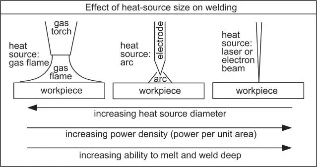
Figure 1.1The size of the heat source and its effect on welding.
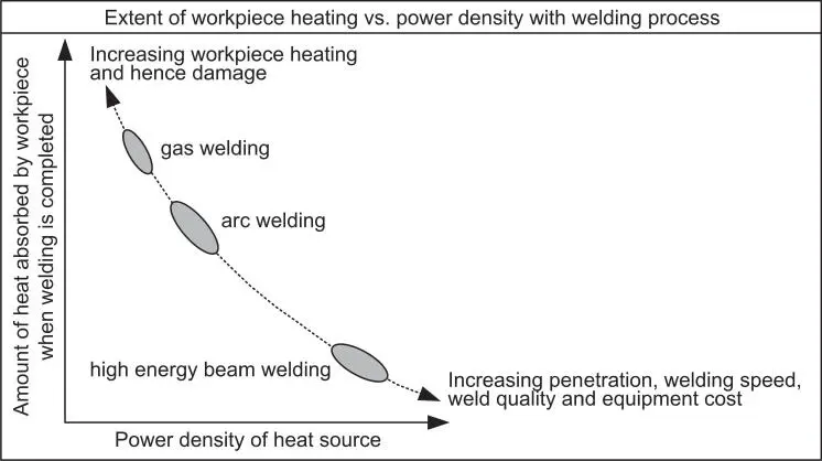
Figure 1.2Heating of and hence damage to workpiece vs. power density of heat source.
Therefore, the advantages of increasing the power density of the heat source include deeper weld penetration, higher welding speed, and better weld quality with less damage to the workpiece, as indicated in Figure 1.2. Figure 1.3shows that the weld strength (of aluminum alloys) increases as the heat input per unit length of the weld per unit thickness of the workpiece decreases [2]. Figure 1.4a shows that the angular distortion of the workpiece is much smaller in EBW than in GTAW [2]. Unfortunately, as shown in Figure 1.4b, the costs of laser and EBW machines are very high [2]. This higher equipment cost is also shown in Figure 1.2.
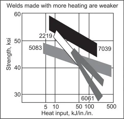
Figure 1.3Variation of weld strength with heat input per unit length of weld per unit thickness of workpiece.
Читать дальше
