Mount Sinai Expert Guides
Здесь есть возможность читать онлайн «Mount Sinai Expert Guides» — ознакомительный отрывок электронной книги совершенно бесплатно, а после прочтения отрывка купить полную версию. В некоторых случаях можно слушать аудио, скачать через торрент в формате fb2 и присутствует краткое содержание. Жанр: unrecognised, на английском языке. Описание произведения, (предисловие) а так же отзывы посетителей доступны на портале библиотеки ЛибКат.
- Название:Mount Sinai Expert Guides
- Автор:
- Жанр:
- Год:неизвестен
- ISBN:нет данных
- Рейтинг книги:4 / 5. Голосов: 1
-
Избранное:Добавить в избранное
- Отзывы:
-
Ваша оценка:
Mount Sinai Expert Guides: краткое содержание, описание и аннотация
Предлагаем к чтению аннотацию, описание, краткое содержание или предисловие (зависит от того, что написал сам автор книги «Mount Sinai Expert Guides»). Если вы не нашли необходимую информацию о книге — напишите в комментариях, мы постараемся отыскать её.
Mount Sinai Expert Guides — читать онлайн ознакомительный отрывок
Ниже представлен текст книги, разбитый по страницам. Система сохранения места последней прочитанной страницы, позволяет с удобством читать онлайн бесплатно книгу «Mount Sinai Expert Guides», без необходимости каждый раз заново искать на чём Вы остановились. Поставьте закладку, и сможете в любой момент перейти на страницу, на которой закончили чтение.
Интервал:
Закладка:
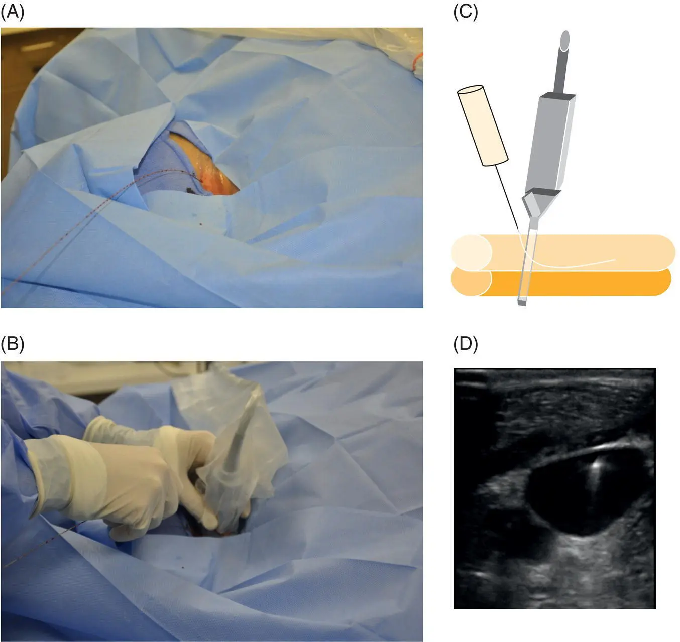
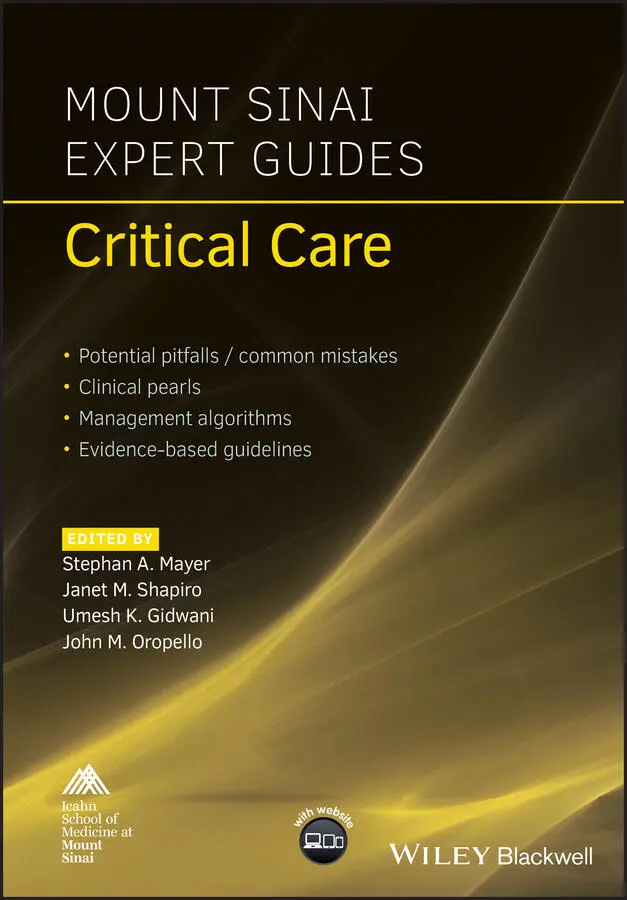
Figure 3.5 Ultrasound of the guidewire. (A) Following cannulation of the vein the guidewire is passed through the introducer needle and the needle is removed. (B) The ultrasound is again placed at the insertion site to visualize the guidewire (C) and confirm that the guidewire is in the vein and not in the artery (D) before dilation of the vessel is performed.
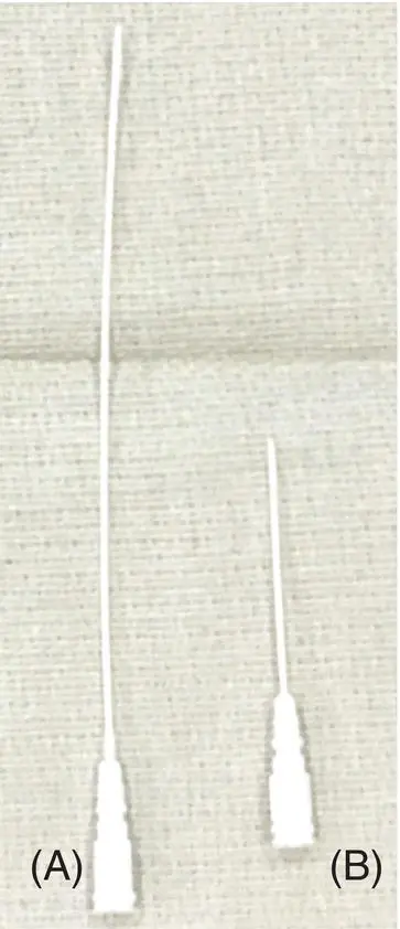
Figure 3.6 Arterial line catheter types. (A) Longer catheter (12 cm) used for axillary or femoral arterial lines. (B) Shorter catheter (4.5 cm) used for radial arterial lines.
Figure 3.7 Arterial line catheter types. (A) Angiocatheter. (B) Assembly (needle, angiocath, and guidewire incorporated into a single unit). (C, D) Guidewire and introducer needle separately.
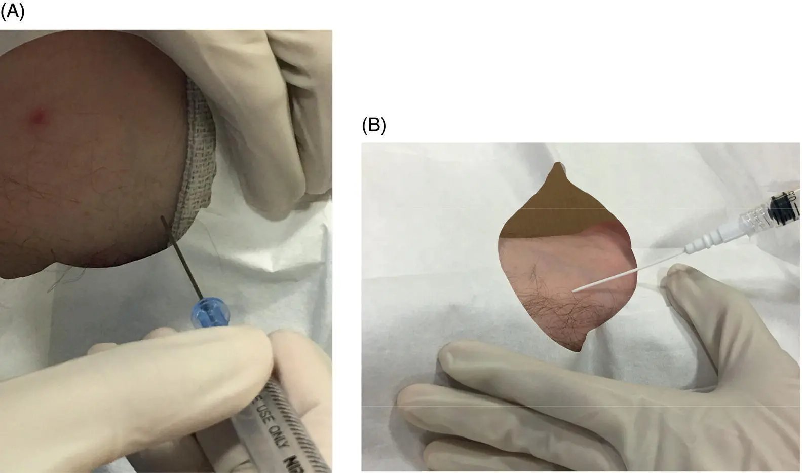
Figure 3.8 Introducer needle angles for arterial catheter insertion. (A) Axillary line cannulation with needle positioning shown at a steeper angle (70–80°). This steeper angle is used to improve visualization of the needle tip under ultrasound (not shown) in the larger axillary or femoral vessels. (B) Radial line cannulation with needle positioning shown at a more shallow angle (e.g. 45° or less) to avoid penetrating the posterior wall of this small artery.
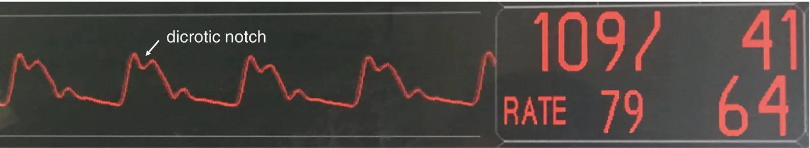
Figure 3.9 Arterial line waveform with peak wave followed by dicrotic notch. An adequate waveform (e.g. not damped) should be confirmed before suturing the catheter in place.
Additional material for this chapter can be found online at:
www.wiley.com/go/mayer/mountsinai/criticalcare
This includes multiple choice questions and Videos 3.1, 3.2 and 3.3. 
CHAPTER 4 Bedside Ultrasound
Daisi Choi1 and John M. Oropello2
1Weill Cornell School of Medicine, New York, NY, USA
2Icahn School of Medicine at Mount Sinai, New York, NY, USA
OVERALL BOTTOM LINE
Bedside US is a safe, non‐invasive diagnostic procedure that allows rapid evaluation of undifferentiated hypotension and identification of reversible causes of shock. It is also a useful tool for promptly excluding immediately life‐threatening emergencies.
The focused assessment using sonography for trauma (FAST) exam is the standard of care in the initial evaluation of trauma patients with hypotension or signs of shock. Until recently, there was no standardized sonographic approach for evaluating the critically ill medical patient.
In 2009, the American College of Chest Physicians produced a consensus statement describing competence in critical care US. The components of critical care US the intensivist should achieve competence in for routine ICU operations include the following:Critical care echocardiography.Pleural ultrasonography.Lung ultrasonography.Abdominal ultrasonography.Vascular ultrasonography: guidance of vascular access and diagnosis of venous thrombosis.
Indications
Initial evaluation of undifferentiated hypotension and shock.
Non‐invasive monitoring of hemodynamic status and following response to therapy.
Respiratory failure.
Cardiac arrest.
Vascular access.
Basic concepts
Ultrasound physics ( Table 4.1)
Sound waves: series of mechanical pressure waves that require a medium to travel through.
US waves undergo attenuation, reflection, refraction, and scattering as they travel through tissue.
Acoustic impedance: resistance of tissue to passage of US waves.
Degree of reflection is determined by difference in acoustic impedance of two tissues at interface.
US image is formed from reflected echoes.
Table 4.1 Features of ultrasound physics.
| Body tissue | Acoustic impedance | Degree of reflection |
|---|---|---|
| Air | Very low | High |
| Liver, blood, kidney | ‘Average’ soft tissue | Low |
| Bone | Very high | High |
Table 4.2 Probe types.
| Linear array probe | Phased array probe | Large curvilinear probe |
|---|---|---|
| Commonly referred to as vascular probe High frequency (typically 5–10 MHz)Large footprintExcellent image resolution of superficial structures at expense of tissue penetrationUse: vascular, lung (specifically pleura) | Commonly referred to as cardiac probe Small footprint; sound waves originate from single point and fan outwardLow frequency (typically 1–5 MHz)Excellent tissue penetration at expense of image resolutionUse: cardiac, lung, abdomen | Large footprint; sound waves originate from large area and fan outwardLow frequency (typically 2–5 MHz)Excellent tissue penetration at expense of image resolutionUse: abdomen |
Ultrasound equipment
Transducer (probe): sends out US waves that pass through tissue; also senses sound waves reflected back to transducer.
Structures closest to transducer are displayed at top of US screen in ‘near field.’
All probes have an ‘indicator’ (typically a bump or groove) on one side of the transducer that corresponds to an index marker on the US screen. Types of probes: see Figure 4.1and Table 4.2.
General radiology convention is to position the screen index marker on left side of screen, and ‘point’ the probe indicator to patient’s right side or head. This means images on left side of screen correspond to structures on patient’s right side or toward patient’s head, respectively.
Cardiologists use an opposite convention (discussed in more depth in Procedure section).
It is critical to confirm your probe orientation with gel prior to any US exam or procedure. Relative to you, with the probe placed just above the intended point of contact, tapping under the right side of the probe should result in movement on the right side of the ultrasound screen. If movement occurs on the left side of the screen, rotate the probe 180°.
Basic knobology
Depth: adjusts depth of field of view by increasing or decreasing depth of US beam. Increasing depth will visualize deeper structures and decreasing will enlarge superficial structures.
Gain: adjusts brightness of image by changing amplification of returning echoes.
Time‐gain compensation: adjusts gain at selective depths to account for tissue attenuation; echoes returning from deeper tissues will be weaker.
Freeze: creates ‘still’ or ‘frozen’ 2D images.
Читать дальшеИнтервал:
Закладка:
Похожие книги на «Mount Sinai Expert Guides»
Представляем Вашему вниманию похожие книги на «Mount Sinai Expert Guides» списком для выбора. Мы отобрали схожую по названию и смыслу литературу в надежде предоставить читателям больше вариантов отыскать новые, интересные, ещё непрочитанные произведения.


Обсуждение, отзывы о книге «Mount Sinai Expert Guides» и просто собственные мнения читателей. Оставьте ваши комментарии, напишите, что Вы думаете о произведении, его смысле или главных героях. Укажите что конкретно понравилось, а что нет, и почему Вы так считаете.