Position, Navigation, and Timing Technologies in the 21st Century
Здесь есть возможность читать онлайн «Position, Navigation, and Timing Technologies in the 21st Century» — ознакомительный отрывок электронной книги совершенно бесплатно, а после прочтения отрывка купить полную версию. В некоторых случаях можно слушать аудио, скачать через торрент в формате fb2 и присутствует краткое содержание. Жанр: unrecognised, на английском языке. Описание произведения, (предисловие) а так же отзывы посетителей доступны на портале библиотеки ЛибКат.
- Название:Position, Navigation, and Timing Technologies in the 21st Century
- Автор:
- Жанр:
- Год:неизвестен
- ISBN:нет данных
- Рейтинг книги:5 / 5. Голосов: 1
-
Избранное:Добавить в избранное
- Отзывы:
-
Ваша оценка:
Position, Navigation, and Timing Technologies in the 21st Century: краткое содержание, описание и аннотация
Предлагаем к чтению аннотацию, описание, краткое содержание или предисловие (зависит от того, что написал сам автор книги «Position, Navigation, and Timing Technologies in the 21st Century»). Если вы не нашли необходимую информацию о книге — напишите в комментариях, мы постараемся отыскать её.
Volume 1 of
contains three parts and focuses on the satellite navigation systems, technologies, and engineering and scientific applications. It starts with a historical perspective of GPS development and other related PNT development. Current global and regional navigation satellite systems (GNSS and RNSS), their inter-operability, signal quality monitoring, satellite orbit and time synchronization, and ground- and satellite-based augmentation systems are examined. Recent progresses in satellite navigation receiver technologies and challenges for operations in multipath-rich urban environment, in handling spoofing and interference, and in ensuring PNT integrity are addressed. A section on satellite navigation for engineering and scientific applications finishes off the volume.
Volume 2 of
consists of three parts and addresses PNT using alternative signals and sensors and integrated PNT technologies for consumer and commercial applications. It looks at PNT using various radio signals-of-opportunity, atomic clock, optical, laser, magnetic field, celestial, MEMS and inertial sensors, as well as the concept of navigation from Low-Earth Orbiting (LEO) satellites. GNSS-INS integration, neuroscience of navigation, and animal navigation are also covered. The volume finishes off with a collection of work on contemporary PNT applications such as survey and mobile mapping, precision agriculture, wearable systems, automated driving, train control, commercial unmanned aircraft systems, aviation, and navigation in the unique Arctic environment.
In addition, this text:
Serves as a complete reference and handbook for professionals and students interested in the broad range of PNT subjects Includes chapters that focus on the latest developments in GNSS and other navigation sensors, techniques, and applications Illustrates interconnecting relationships between various types of technologies in order to assure more protected, tough, and accurate PNT
will appeal to all industry professionals, researchers, and academics involved with the science, engineering, and applications of position, navigation, and timing technologies.pnt21book.com
Position, Navigation, and Timing Technologies in the 21st Century — читать онлайн ознакомительный отрывок
Ниже представлен текст книги, разбитый по страницам. Система сохранения места последней прочитанной страницы, позволяет с удобством читать онлайн бесплатно книгу «Position, Navigation, and Timing Technologies in the 21st Century», без необходимости каждый раз заново искать на чём Вы остановились. Поставьте закладку, и сможете в любой момент перейти на страницу, на которой закончили чтение.
Интервал:
Закладка:
Source: Reproduced with permission of Z. Kassas (International Technical Meeting Conference).
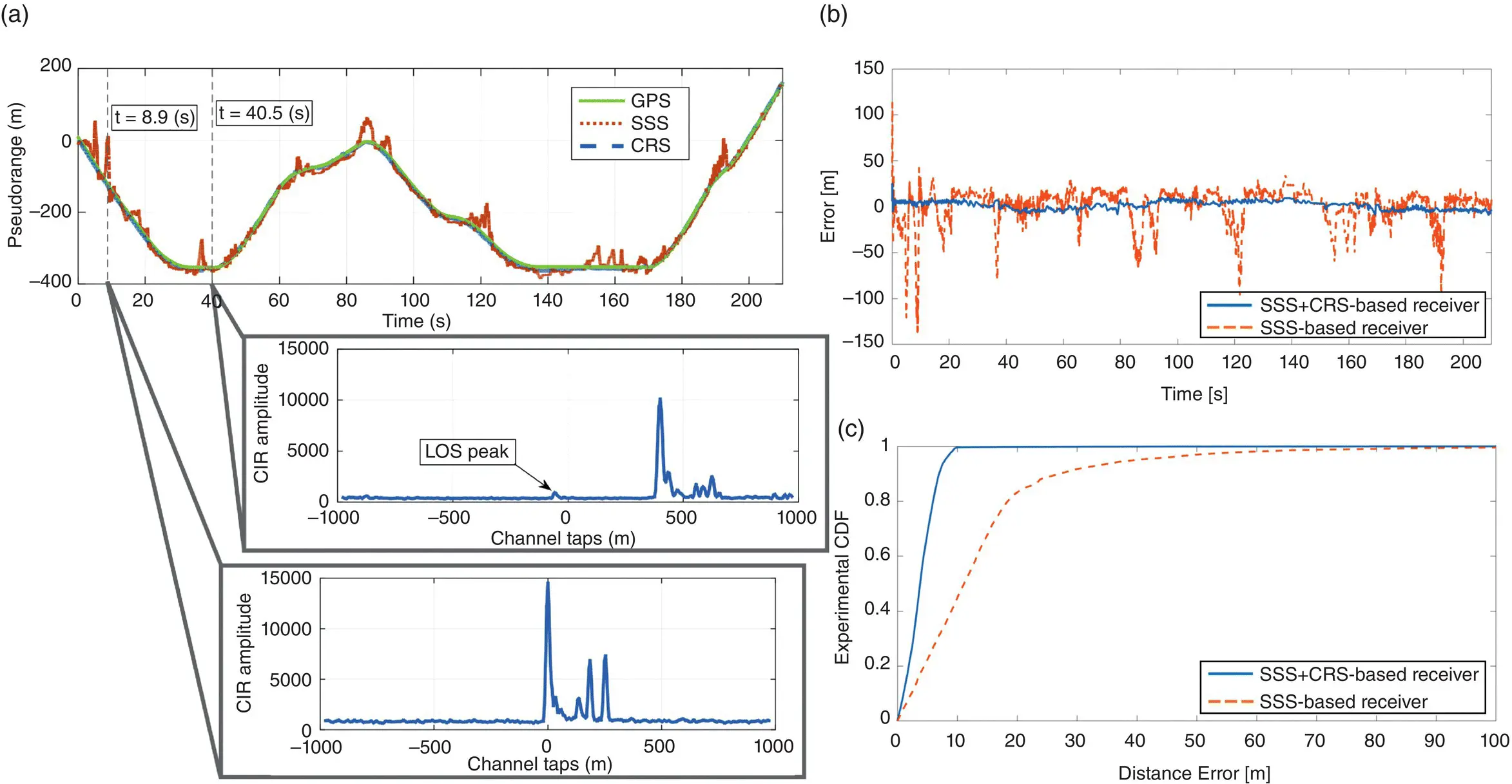
Figure 38.51 (a) Estimated change in pseudorange and estimated CIR at t = 8.89 s and t = 40.5 s for eNodeB 2. The change in the pseudorange was calculated using (1) SSS pseudoranges, (2) CRS pseudoranges, and (3) true ranges obtained using GPS. (b) Pseudorange error between (1) GPS and SSS and (2) GPS and SSS+CRS. (c) CDF of the error in (b) (Shamaei et al. [63]).
Source: Reproduced with permission of Z. Kassas (International Technical Meeting Conference).
The error in the pseudorange obtained by tracking the SSS is mainly due to multipath. The estimated CIR at t = 13.04 s for eNodeB 1 and t = 8.89 s and t = 40.5 s for eNodeB 2 show several peaks due to multipath, which are dominating the line‐of‐sight (LoS) peak. These peaks contributed a pseudorange error of around 330 m at t = 13.04 s for eNodeB 1 and around 130 m at t = 8.89 s for eNodeB 2. These results highlight the importance of utilizing the CRS signals to correct for multipath‐induced errors.
38.6.4.2 Ground Vehicle Navigation
A car was equipped with the cellular LTE navigation receiver discussed in Section 38.6.2. The receiver was tuned to the cellular carrier frequencies 739 MHz and 1955 MHz, which are used by the US cellular provider AT&T. The PLL, FLL, and DLL noise‐equivalent bandwidths were set to 4, 0.2, and 0.001 Hz, respectively. The adaptive threshold approach proposed in [65] was adopted to mitigate multipath.
All measurements and trajectories were projected onto a 2D plane. It was assumed that the receiver had access to GPS, and GPS was cut off at the start time of the experiment. Therefore, the EKF’s states were initialized with the values obtained from the GPS navigation solution. The standard deviation of the initial uncertainty of position and velocity were set to be 5 m and 0.01 m/s, respectively [55]. The standard deviation of the initial uncertainty of the clock bias and drift were set to be 0.1 m and 0.01 m/s, which were obtained empirically. The clock oscillators were modeled as oven‐controlled crystal oscillators (OCXOs) with  and
and 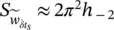 , where h 0= 2.6 × 10 −22and h −2= 4 × 10 −26. The power spectral densities
  and
and  were set to 0.2 m 2/s 3, and the measurement noise covariance was set to be 10 m 2, which were obtained empirically. The vehicle was listening to six eNodeBs whose position states were mapped beforehand. The cell IDs of the eNodeBs were 216, 489, 457, 288, 232, 152, respectively. The first three eNodeBs had a 20 MHz transmission bandwidth, and the rest of the eNodeBs had a 10 MHz transmission bandwidth. The C / N 0for all received eNodeB signals was between 50 and 68 dB‐Hz. The experimental hardware setup, the environment layout, and the true and estimated navigator trajectories are shown in Figure 38.52. The ground‐truth trajectory was obtained from the GRID GPS SDR [58].
38.6.4.3 Aerial Vehicle Navigation
A UAV was equipped with the cellular LTE navigation receiver discussed in Section 38.6.2. When a UAV flies high enough, the received signal to the UAV does not experience multipath from the surrounding environment, except from the UAV’s body. Here, the multipath effect from the UAV’s body is negligible; therefore, tracking only the SSS yields good results, and the CRS was not used. This significantly decreases the computational burden in the receiver. It also reduces the need for a high sampling rate, which lowers the hardware cost and size. The receiver was tuned to the cellular carrier frequency of 1955 MHz, which is used by the US cellular provider AT&T.
Over the course of the experiment, the UAV was flying at an altitude of 40 m. The receiver was listening to three eNodeBs, each of which had two transmitting antennas with 20 MHz transmission bandwidth. The positions of the eNodeBs were mapped prior to the experiment with approximately 2 m accuracy. All measurements and trajectories were projected onto a 2D plane. Subsequently, only the horizontal position of the receiver was estimated. It was assumed that the receiver had access to GPS, and GPS was cut off at the start time of the experiment. Therefore, the EKF’s states were initialized with the values obtained from the GPS navigation solution. The EKF process noise and measurement noise covariances were set in a similar manner to the ground vehicle navigation experiment. The environment layout as well as the true and estimated receiver trajectories are shown in Figure 38.53. It can be seen from Figure 38.53that the navigation solution obtained from LTE signals closely follows the GPS navigation solution. The ground‐truth trajectory was obtained from the GRID GPS SDR [58].
In an urban environment, the pseudoranges received by a ground vehicle will suffer from more multipath‐induced error compared to the pseudoranges received by a UAV with LoS conditions. However, this comparison can be made as long as the ground vehicle and UAV are navigating in the same environment, using the same eNodeBs, and following the same trajectories, except that one is on the ground while the other is airborne. In the results presented in Figures 38.52and 38.53, the ground vehicle was equipped with a better USRP than the one on the UAV, due to payload limitations. Consequently, the LTE receiver onboard the ground vehicle was able to listen to more eNodeBs than the receiver onboard the UAV, providing the former with more measurements at a better geometric diversity than the latter. Moreover, the UAV did not use the CRS signals, which were used by the ground vehicle to aid its SSS tracking loops. These aforementioned factors resulted in the position root‐mean‐squared error (RMSE) of the ground vehicle being less than the position RMSE of the UAV.
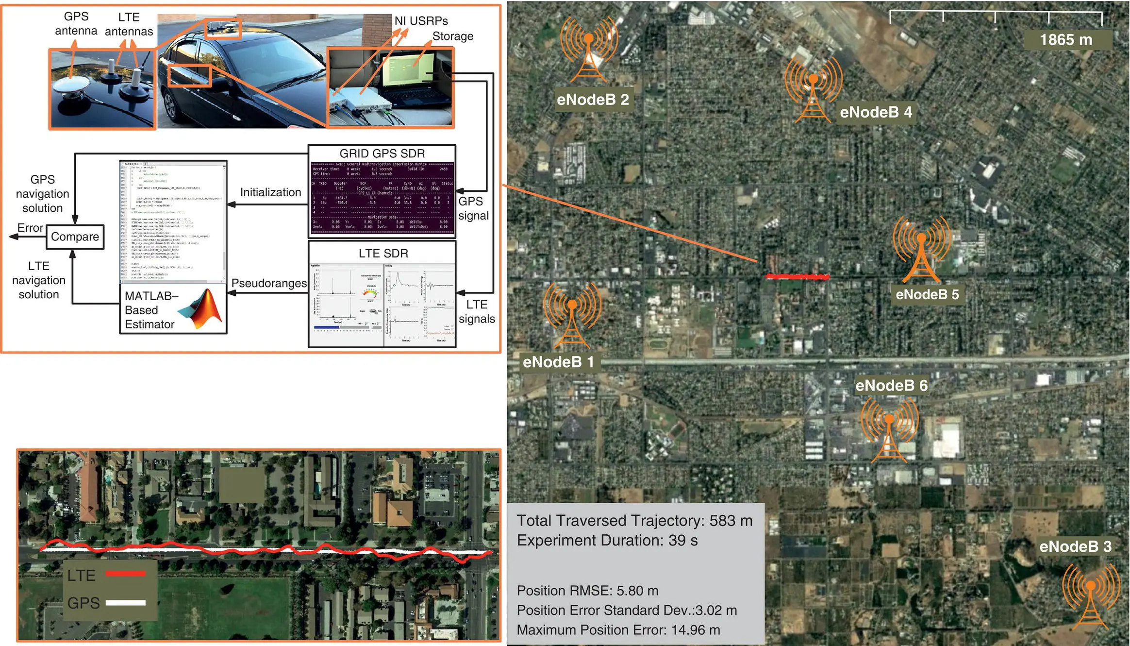
Figure 38.52 (a) Experimental hardware and software setup and environment layout in downtown Riverside, California, showing eNodeBs’ locations and the traversed trajectory as estimated by GPS and LTE signals.
Map data: Google Earth (Shamaei et al. [65]). Source: Reproduced with permission of IEEE.
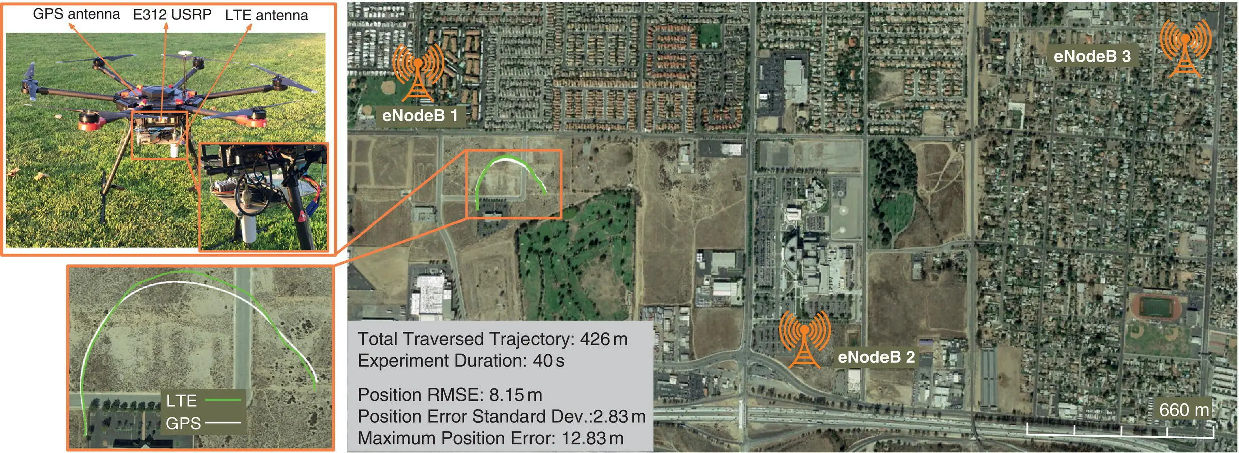
Figure 38.53 Experimental hardware setup and environment layout in Riverside, California, showing eNodeBs’ locations and the traversed trajectory as estimated by GPS and LTE signals.
Map data: Google Earth (Shamaei et al. [65]). Source: Reproduced with permission of IEEE.
38.7 BTS Sector Clock Bias Mismatch
Интервал:
Закладка:
Похожие книги на «Position, Navigation, and Timing Technologies in the 21st Century»
Представляем Вашему вниманию похожие книги на «Position, Navigation, and Timing Technologies in the 21st Century» списком для выбора. Мы отобрали схожую по названию и смыслу литературу в надежде предоставить читателям больше вариантов отыскать новые, интересные, ещё непрочитанные произведения.


Обсуждение, отзывы о книге «Position, Navigation, and Timing Technologies in the 21st Century» и просто собственные мнения читателей. Оставьте ваши комментарии, напишите, что Вы думаете о произведении, его смысле или главных героях. Укажите что конкретно понравилось, а что нет, и почему Вы так считаете.