Position, Navigation, and Timing Technologies in the 21st Century
Здесь есть возможность читать онлайн «Position, Navigation, and Timing Technologies in the 21st Century» — ознакомительный отрывок электронной книги совершенно бесплатно, а после прочтения отрывка купить полную версию. В некоторых случаях можно слушать аудио, скачать через торрент в формате fb2 и присутствует краткое содержание. Жанр: unrecognised, на английском языке. Описание произведения, (предисловие) а так же отзывы посетителей доступны на портале библиотеки ЛибКат.
- Название:Position, Navigation, and Timing Technologies in the 21st Century
- Автор:
- Жанр:
- Год:неизвестен
- ISBN:нет данных
- Рейтинг книги:5 / 5. Голосов: 1
-
Избранное:Добавить в избранное
- Отзывы:
-
Ваша оценка:
Position, Navigation, and Timing Technologies in the 21st Century: краткое содержание, описание и аннотация
Предлагаем к чтению аннотацию, описание, краткое содержание или предисловие (зависит от того, что написал сам автор книги «Position, Navigation, and Timing Technologies in the 21st Century»). Если вы не нашли необходимую информацию о книге — напишите в комментариях, мы постараемся отыскать её.
Volume 1 of
contains three parts and focuses on the satellite navigation systems, technologies, and engineering and scientific applications. It starts with a historical perspective of GPS development and other related PNT development. Current global and regional navigation satellite systems (GNSS and RNSS), their inter-operability, signal quality monitoring, satellite orbit and time synchronization, and ground- and satellite-based augmentation systems are examined. Recent progresses in satellite navigation receiver technologies and challenges for operations in multipath-rich urban environment, in handling spoofing and interference, and in ensuring PNT integrity are addressed. A section on satellite navigation for engineering and scientific applications finishes off the volume.
Volume 2 of
consists of three parts and addresses PNT using alternative signals and sensors and integrated PNT technologies for consumer and commercial applications. It looks at PNT using various radio signals-of-opportunity, atomic clock, optical, laser, magnetic field, celestial, MEMS and inertial sensors, as well as the concept of navigation from Low-Earth Orbiting (LEO) satellites. GNSS-INS integration, neuroscience of navigation, and animal navigation are also covered. The volume finishes off with a collection of work on contemporary PNT applications such as survey and mobile mapping, precision agriculture, wearable systems, automated driving, train control, commercial unmanned aircraft systems, aviation, and navigation in the unique Arctic environment.
In addition, this text:
Serves as a complete reference and handbook for professionals and students interested in the broad range of PNT subjects Includes chapters that focus on the latest developments in GNSS and other navigation sensors, techniques, and applications Illustrates interconnecting relationships between various types of technologies in order to assure more protected, tough, and accurate PNT
will appeal to all industry professionals, researchers, and academics involved with the science, engineering, and applications of position, navigation, and timing technologies.pnt21book.com
Position, Navigation, and Timing Technologies in the 21st Century — читать онлайн ознакомительный отрывок
Ниже представлен текст книги, разбитый по страницам. Система сохранения места последней прочитанной страницы, позволяет с удобством читать онлайн бесплатно книгу «Position, Navigation, and Timing Technologies in the 21st Century», без необходимости каждый раз заново искать на чём Вы остановились. Поставьте закладку, и сможете в любой момент перейти на страницу, на которой закончили чтение.
Интервал:
Закладка:
After obtaining the frame timing, the UE estimates the frequency shift (Doppler frequency) using the CP in the received signal r ( n ). The apparent Doppler frequency, including the carrier frequency offset due to clock drift and the Doppler shift, can be estimated by the CP as
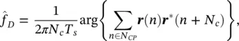
where N CPis the set of CP indices, and T sis the sampling interval [69]. Upon estimating the Doppler frequency, the acquisition of the LTE signal is complete. Figure 38.31summarizes the LTE signal acquisition process.
The normalized correlation of received LTE signals with locally generated PSS and SSS signals are presented in Figure 38.32. It can be seen that since the PSS is transmitted twice per frame, the correlation has two peaks in the duration of one frame, which is 10 ms. However, the SSS correlation has only one peak, since the SSS is transmitted only once per frame. The figure also shows that the highest PSS correlation peak was at  , and the highest SSS correlation peak was at
  . Therefore, the cell ID was calculated to be
 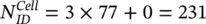 .
.
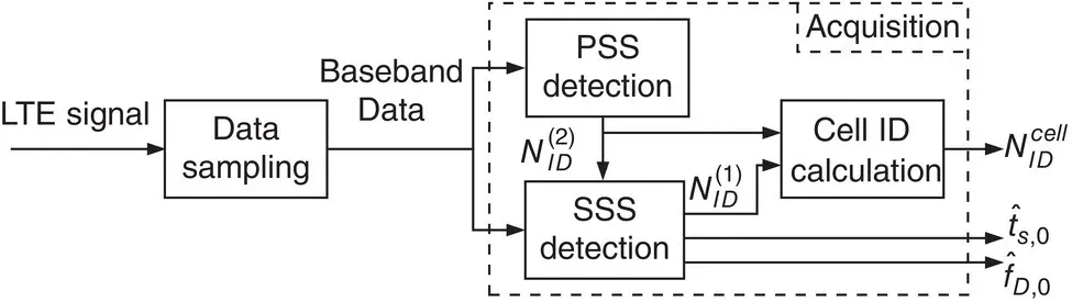
Figure 38.31 Signal acquisition block diagram (Shamaei et al. [64, 65]).
Source: Reproduced with permission of Institute of Navigation, IEEE.

Figure 38.32 PSS and SSS normalized correlation results with real LTE signals (Shamaei et al. [64, 65]).
Source: Reproduced with permission of Institute of Navigation, IEEE.
38.6.2.2 System Information Extraction
Parameters relevant for navigation purposes include the system bandwidth, number of transmitting antennas, and neighboring cell IDs. These parameters are provided to the UE in two blocks, namely, the master information block (MIB) and the system information block (SIB).
The UE starts acquiring with the lowest possible bandwidth of LTE, since it has no information about the actual transmission bandwidth. After acquisition, the signal is converted to the frame, and the bandwidth is obtained by decoding the MIB. Then, the UE can increase its sampling frequency to exploit the high bandwidth of the CRS. The UE can also utilize signals received from multiple eNodeB antennas to improve the TOA estimate.
Since the frequency reuse factor in LTE is 1, it may not be possible to acquire the received PSS and SSS signals from eNodeBs with low C / N 0. This phenomenon is called the near‐far effect. In this case, one can use the neighboring cell IDs obtained by decoding the SIB to reconstruct the CRS sequence [65]. This section discusses the decoding of MIB and SIB.
MIB Decoding:In order to exploit the high‐bandwidth CRS signal, which improves the navigation performance in multipath environments and in the presence of interference, the UE must first reconstruct the LTE frame from the received signal. To do so, the actual transmission bandwidth and number of transmitting antennas, which are provided in the MIB, must be decoded. The MIB is transmitted on the physical broadcast channel (PBCH) and consists of 24 bits of data: 3 bits for downlink bandwidth, 3 bits for frame number, and 18 bits for other information and spare bits. The MIB is coded and transmitted on four consecutive symbols of a frame’s second slot. However, it is not transmitted in REs reserved for the reference signals. Figure 38.33shows the steps the MIB message goes through before transmission [61, 70].
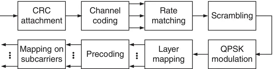
Figure 38.33 MIB coding process (Shamaei et al. [65]).
Source: Reproduced with permission of IEEE.
In the first step, a CRC of length L = 16 is obtained using the cyclic generator polynomial g CRC( D ) = D 16+ D 12+ D 5+ 1. The number of transmitting antennas is not transmitted in the 24‐bit MIB message. Instead, this information is provided in the CRC mask, which is a sequence used to scramble the CRC bits appended to the MIB. The CRC mask is either all zeros, all ones, or [0, 1, 0, ⋯, 0, 1] for 1, 2, or 4 transmitting antennas, respectively. In order to obtain the number of transmitting antennas from the received signal, the UE needs to perform a blind search over the number of all possible transmitting antennas. Then, by comparing the locally generated CRC scrambled by the CRC mask with the received CRC, the number of transmitting antennas is identified.
In the second step, channel coding is performed using a convolutional encoder with constraint length 7 and coding rate 1/3. The configuration of the encoder is shown in Figure 38.34. The initial value of the encoder is set to the value of the last six information bits in the input stream. The method illustrated in Figure 38.35is used to decode the received signal [71]. In this method, the received signal is repeated once. Then, a Viterbi decoder is executed on the resulting sequence. Finally, the middle part of the sequence is selected and circularly shifted.
In the next step, the convolutional coded bits are rate‐matched. In the rate matching step, the obtained data from channel coding is first interleaved. Then, the outcomes of interleaving each stream are repeated to obtain a 1920‐bit‐long array [70]. Next, the output of the rate matching step is scrambled with a pseudorandom sequence, which is initialized with the cell ID, yielding unique signal detection for all eNodeBs. Subsequently, QPSK is performed on the obtained data, resulting in 960 symbols which are mapped onto different layers to provide transmission diversity. To overcome channel fading and thermal noise, space‐time coding is utilized. This process is performed in the precoding step. Finally, the resulting symbols are mapped onto the predetermined subcarriers for MIB transmission [70].
SIB Decoding:When a UE performs acquisition, it obtains the cell ID of the ambient eNodeB with the highest power, referred to as the main eNodeB. For navigation purposes, the UE needs access to multiple eNodeB signals to estimate its state. One solution is to perform the acquisition for all the possible values of  . However, this method limits the number of intra‐frequency eNodeBs that a UE can simultaneously use for positioning. The second solution is to provide a database of the network to the UE. In this method, the UE needs to search over all possible values of the cell IDs to acquire the right ones unless the UE knows its current position, which is not a practical assumption. The other solution, which is more reliable and overcomes the aforementioned problem, is to extract the neighboring cell IDs using the information provided in the SIB transmitted by the main eNodeB. Since other operators transmit on different carrier frequencies, the same approach can be exploited to extract the cell IDs of the neighboring eNodeBs from other operators. Knowing the eNodeBs’ cell IDs, the receiver only needs to know the position of the eNodeBs using a database or pre‐mapping approaches [37, 39].
Интервал:
Закладка:
Похожие книги на «Position, Navigation, and Timing Technologies in the 21st Century»
Представляем Вашему вниманию похожие книги на «Position, Navigation, and Timing Technologies in the 21st Century» списком для выбора. Мы отобрали схожую по названию и смыслу литературу в надежде предоставить читателям больше вариантов отыскать новые, интересные, ещё непрочитанные произведения.


Обсуждение, отзывы о книге «Position, Navigation, and Timing Technologies in the 21st Century» и просто собственные мнения читателей. Оставьте ваши комментарии, напишите, что Вы думаете о произведении, его смысле или главных героях. Укажите что конкретно понравилось, а что нет, и почему Вы так считаете.