Position, Navigation, and Timing Technologies in the 21st Century
Здесь есть возможность читать онлайн «Position, Navigation, and Timing Technologies in the 21st Century» — ознакомительный отрывок электронной книги совершенно бесплатно, а после прочтения отрывка купить полную версию. В некоторых случаях можно слушать аудио, скачать через торрент в формате fb2 и присутствует краткое содержание. Жанр: unrecognised, на английском языке. Описание произведения, (предисловие) а так же отзывы посетителей доступны на портале библиотеки ЛибКат.
- Название:Position, Navigation, and Timing Technologies in the 21st Century
- Автор:
- Жанр:
- Год:неизвестен
- ISBN:нет данных
- Рейтинг книги:5 / 5. Голосов: 1
-
Избранное:Добавить в избранное
- Отзывы:
-
Ваша оценка:
Position, Navigation, and Timing Technologies in the 21st Century: краткое содержание, описание и аннотация
Предлагаем к чтению аннотацию, описание, краткое содержание или предисловие (зависит от того, что написал сам автор книги «Position, Navigation, and Timing Technologies in the 21st Century»). Если вы не нашли необходимую информацию о книге — напишите в комментариях, мы постараемся отыскать её.
Volume 1 of
contains three parts and focuses on the satellite navigation systems, technologies, and engineering and scientific applications. It starts with a historical perspective of GPS development and other related PNT development. Current global and regional navigation satellite systems (GNSS and RNSS), their inter-operability, signal quality monitoring, satellite orbit and time synchronization, and ground- and satellite-based augmentation systems are examined. Recent progresses in satellite navigation receiver technologies and challenges for operations in multipath-rich urban environment, in handling spoofing and interference, and in ensuring PNT integrity are addressed. A section on satellite navigation for engineering and scientific applications finishes off the volume.
Volume 2 of
consists of three parts and addresses PNT using alternative signals and sensors and integrated PNT technologies for consumer and commercial applications. It looks at PNT using various radio signals-of-opportunity, atomic clock, optical, laser, magnetic field, celestial, MEMS and inertial sensors, as well as the concept of navigation from Low-Earth Orbiting (LEO) satellites. GNSS-INS integration, neuroscience of navigation, and animal navigation are also covered. The volume finishes off with a collection of work on contemporary PNT applications such as survey and mobile mapping, precision agriculture, wearable systems, automated driving, train control, commercial unmanned aircraft systems, aviation, and navigation in the unique Arctic environment.
In addition, this text:
Serves as a complete reference and handbook for professionals and students interested in the broad range of PNT subjects Includes chapters that focus on the latest developments in GNSS and other navigation sensors, techniques, and applications Illustrates interconnecting relationships between various types of technologies in order to assure more protected, tough, and accurate PNT
will appeal to all industry professionals, researchers, and academics involved with the science, engineering, and applications of position, navigation, and timing technologies.pnt21book.com
Position, Navigation, and Timing Technologies in the 21st Century — читать онлайн ознакомительный отрывок
Ниже представлен текст книги, разбитый по страницам. Система сохранения места последней прочитанной страницы, позволяет с удобством читать онлайн бесплатно книгу «Position, Navigation, and Timing Technologies in the 21st Century», без необходимости каждый раз заново искать на чём Вы остановились. Поставьте закладку, и сможете в любой момент перейти на страницу, на которой закончили чтение.
Интервал:
Закладка:
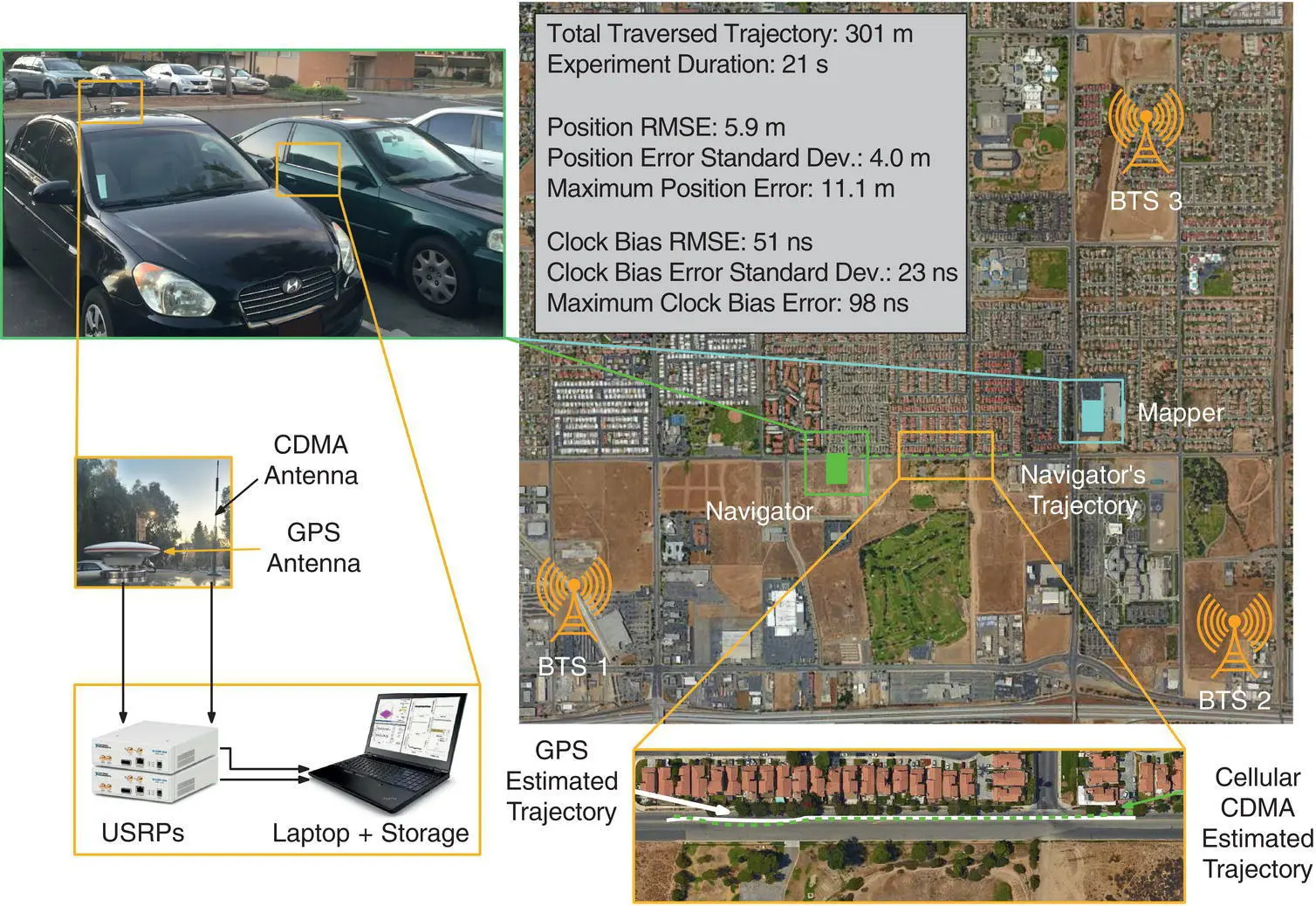
Figure 38.24 Experimental hardware setup, navigator trajectory, and mapper and BTS locations for ground experiment. Map data: Google Earth (Khalife et al. [18]; Khalife and Kassas [25]).
Source: Reproduced with permission of IEEE.
The user’s privacy is compromised, since the user’s location is revealed to the network [60]. Figure 38.25 BTS environment and experimental hardware setup with a mobile mapper. Map data: Google Earth (Khalife and Kassas [25]).Source: Reproduced with permission of IEEE. Figure 38.26 Navigating UAV’s true and estimated trajectory.Map data: Google Earth.
Localization services are limited to paying subscribers and from a particular cellular provider.
Ambient LTE signals transmitted by other cellular providers are not exploited.
Additional bandwidth is required to accommodate the PRS, which caused the majority of cellular providers to choose not to transmit the PRS in favor of dedicating more bandwidth for traffic channels.
To circumvent these drawbacks, UE‐based PNT techniques, which exploit the existing reference signals in the transmitted LTE signals, have been developed. This section focuses on UE‐based PNT techniques. When a UE enters an unknown LTE environment, the first step it performs to establish communication with the network is synchronizing with the surrounding LTE BTSs, also referred to as Evolved Node Bs (eNodeBs). This is achieved by acquiring the PSS and the SSS transmitted by the eNodeB. The PSS and SSS can be directly exploited for navigation. Another LTE signal that can be exploited for navigation is the CRS; however, exploiting CRS is not as straightforward due to its scattered nature in time and frequency. Table 38.1compares the salient navigation properties of PSS, SSS, and CRS.
This section is organized as follows. Section 38.6.1discusses the LTE frame structure and reference signals that could be exploited for navigation. Section 38.6.2presents a receiver architecture for producing navigation observables from received LTE signals. Section 38.6.3analyzes the code phase error of SSS signals with coherent and non‐coherent DLL tracking. Section 38.6.4shows experimental results for ground and aerial vehicles navigating with cellular LTE signals.
38.6.1 LTE Frame and Reference Signal Structure
In LTE downlink transmission, data is encoded using orthogonal frequency division multiplexing (OFDM). OFDM is a transmission method in which the symbols are mapped onto multiple carrier frequencies called subcarriers. The serial data symbols  are first parallelized in groups of length N r, where N rrepresents the number of subcarriers that carry data. Then, each group is zero‐padded to length N c, which is the total number of subcarriers, and an inverse FFT (IFFT) is taken. The value of N cis set to be greater than N rto provide a guard band in the frequency domain. Finally, to protect the data from multipath effects, the last L CPelements of the obtained symbols are repeated at the beginning of the data, called the cyclic prefix (CP). The transmitted symbols can be obtained at the receiver by executing these steps in reverse order. Since the frequency reuse factor in LTE systems is 1, all the eNodeBs of the same operator use the same frequency band. To reduce the interference caused by sharing the same frequency band, each signal is coded to be orthogonal to the transmitted signals from other eNodeBs. Using different frequency bands makes it possible to allocate the same cell IDs to the eNodeBs from different operators. Figure 38.27represents the block diagram of the OFDM encoding scheme for digital transmission. The following subsections discuss the LTE frame structure and reference signals, which will be exploited for navigation.
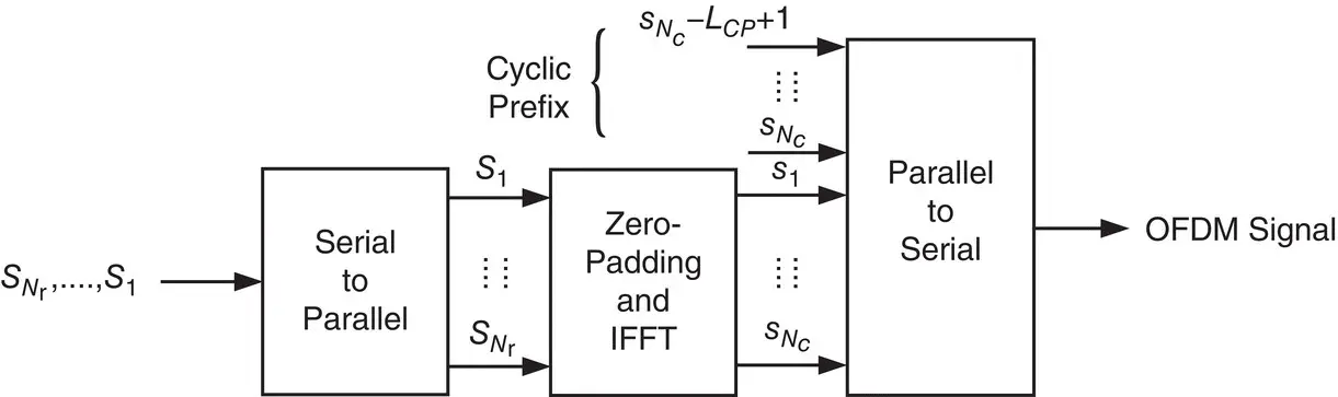
Figure 38.27 OFDM transmission block diagram (Kassas et al. [6]).
Source: Reproduced with permission of IEEE.
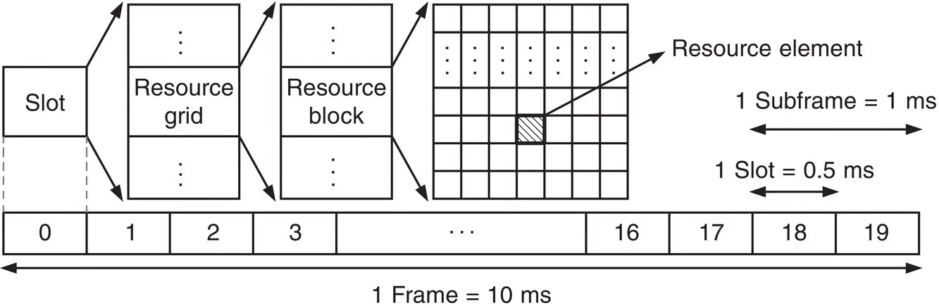
Figure 38.28 LTE frame structure (Shamaei et al. [64, 65]).
Source: Reproduced with permission of Institute of Navigation, IEEE.
38.6.1.1 Frame Structure
The received OFDM signals are arranged in multiple blocks, which are called frames. In an LTE system, the structure of the frame depends on the transmission type, which can be either frequency‐division duplexing (FDD) or time‐division duplexing (TDD). Due to the superior performance of FDD in terms of latency and transmission range, most network providers use FDD for LTE transmission. Hence, this section considers FDD for LTE transmission, and for simplicity, an FDD frame is simply called a frame.
A frame is a major component in LTE communication, which is a 2D grid representing time and frequency. A frame is composed of 10 ms data, which is divided into either 20 slots or 10 subframes with a duration of 0.5 ms or 1 ms, respectively. A slot can be decomposed into multiple resource grids (RGs), and each RG has numerous resource blocks (RBs). Then, an RB is broken down into the smallest elements of the frame, namely, resource elements (REs). The frequency and time indices of an RE are called subcarrier and symbol, respectively. The LTE frame structure is illustrated in Figure 38.28, and the composition of a single LTE frame with six RBs is depicted in Figure 38.29[61].
The number of subcarriers in an LTE frame, N c, and the number of used subcarriers, N r, are assigned by the network provider and can only take the values that are shown in Table 38.4. The subcarrier spacing is typically Δ f = 15 kHz. Hence, the occupied bandwidth W ′ can be calculated using W ′ = N r× Δ f . To allow for a guard band, the allocated bandwidth W is chosen to be slightly higher than the W ′ bandwidth (e.g. W = 1.4 MHz is chosen for a W ′ = 1.08 MHz). Note that N cis chosen to be a power of two to exploit the computational efficiency of the FFT.
When a UE receives an LTE signal, it must reconstruct the LTE frame to be able to extract the information transmitted in the signal. This is achieved by first identifying the frame start time. Then, knowing the frame timing, the receiver can remove the CPs and take the FFT of each N csymbol. The duration of the normal CP is 5.21 μ s for the first symbol of each slot and 4.69 μ s for the rest of the symbols [61]. To determine the frame timing, the PSS and SSS must be acquired, which will be discussed in the next section.
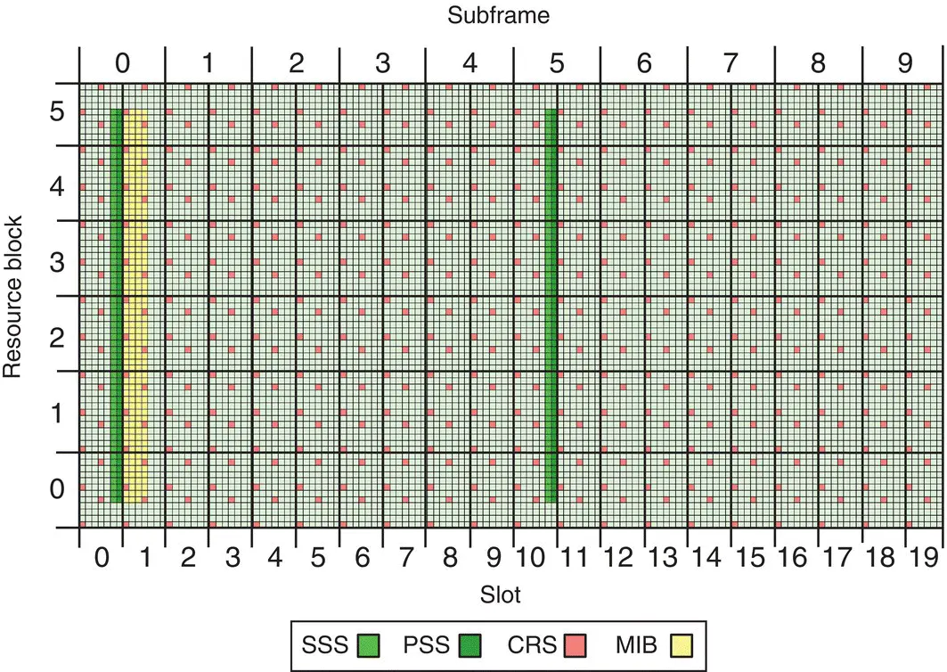
Figure 38.29 Composition of a single LTE frame. The slots represent time, while the RBs represent frequency (Shamaei and Kassas [15]).
Source: Reproduced with permission of Institute of Navigation.
Читать дальшеИнтервал:
Закладка:
Похожие книги на «Position, Navigation, and Timing Technologies in the 21st Century»
Представляем Вашему вниманию похожие книги на «Position, Navigation, and Timing Technologies in the 21st Century» списком для выбора. Мы отобрали схожую по названию и смыслу литературу в надежде предоставить читателям больше вариантов отыскать новые, интересные, ещё непрочитанные произведения.


Обсуждение, отзывы о книге «Position, Navigation, and Timing Technologies in the 21st Century» и просто собственные мнения читателей. Оставьте ваши комментарии, напишите, что Вы думаете о произведении, его смысле или главных героях. Укажите что конкретно понравилось, а что нет, и почему Вы так считаете.