Position, Navigation, and Timing Technologies in the 21st Century
Здесь есть возможность читать онлайн «Position, Navigation, and Timing Technologies in the 21st Century» — ознакомительный отрывок электронной книги совершенно бесплатно, а после прочтения отрывка купить полную версию. В некоторых случаях можно слушать аудио, скачать через торрент в формате fb2 и присутствует краткое содержание. Жанр: unrecognised, на английском языке. Описание произведения, (предисловие) а так же отзывы посетителей доступны на портале библиотеки ЛибКат.
- Название:Position, Navigation, and Timing Technologies in the 21st Century
- Автор:
- Жанр:
- Год:неизвестен
- ISBN:нет данных
- Рейтинг книги:5 / 5. Голосов: 1
-
Избранное:Добавить в избранное
- Отзывы:
-
Ваша оценка:
Position, Navigation, and Timing Technologies in the 21st Century: краткое содержание, описание и аннотация
Предлагаем к чтению аннотацию, описание, краткое содержание или предисловие (зависит от того, что написал сам автор книги «Position, Navigation, and Timing Technologies in the 21st Century»). Если вы не нашли необходимую информацию о книге — напишите в комментариях, мы постараемся отыскать её.
Volume 1 of
contains three parts and focuses on the satellite navigation systems, technologies, and engineering and scientific applications. It starts with a historical perspective of GPS development and other related PNT development. Current global and regional navigation satellite systems (GNSS and RNSS), their inter-operability, signal quality monitoring, satellite orbit and time synchronization, and ground- and satellite-based augmentation systems are examined. Recent progresses in satellite navigation receiver technologies and challenges for operations in multipath-rich urban environment, in handling spoofing and interference, and in ensuring PNT integrity are addressed. A section on satellite navigation for engineering and scientific applications finishes off the volume.
Volume 2 of
consists of three parts and addresses PNT using alternative signals and sensors and integrated PNT technologies for consumer and commercial applications. It looks at PNT using various radio signals-of-opportunity, atomic clock, optical, laser, magnetic field, celestial, MEMS and inertial sensors, as well as the concept of navigation from Low-Earth Orbiting (LEO) satellites. GNSS-INS integration, neuroscience of navigation, and animal navigation are also covered. The volume finishes off with a collection of work on contemporary PNT applications such as survey and mobile mapping, precision agriculture, wearable systems, automated driving, train control, commercial unmanned aircraft systems, aviation, and navigation in the unique Arctic environment.
In addition, this text:
Serves as a complete reference and handbook for professionals and students interested in the broad range of PNT subjects Includes chapters that focus on the latest developments in GNSS and other navigation sensors, techniques, and applications Illustrates interconnecting relationships between various types of technologies in order to assure more protected, tough, and accurate PNT
will appeal to all industry professionals, researchers, and academics involved with the science, engineering, and applications of position, navigation, and timing technologies.pnt21book.com
Position, Navigation, and Timing Technologies in the 21st Century — читать онлайн ознакомительный отрывок
Ниже представлен текст книги, разбитый по страницам. Система сохранения места последней прочитанной страницы, позволяет с удобством читать онлайн бесплатно книгу «Position, Navigation, and Timing Technologies in the 21st Century», без необходимости каждый раз заново искать на чём Вы остановились. Поставьте закладку, и сможете в любой момент перейти на страницу, на которой закончили чтение.
Интервал:
Закладка:
UAV Results: Figure 38.20shows the BTS environment, the UAV trajectory, and the experimental hardware setup. Signals from two cellular BTSs corresponding to the US cellular provider Verizon Wireless were tracked. The BTSs transmitted at a carrier frequency of 883.98 MHz and their positions were mapped prior to the experiment [37, 39]. The ground‐truth reference for the UAV trajectory shown in Figure 38.20was taken from its onboard navigation system, which uses GPS, an INS, and other sensors. The distance D between the UAV and each BTS was calculated using the navigation solution produced by the UAV’s navigation system and the known BTS position. The pseudorange ρ was obtained from the cellular CDMA receiver that was mounted on the UAV. In order to validate the resulting pseudoranges, the variation of the pseudorange Δ ρ ≜ ρ − ρ (0) and the variation in distance Δ D ≜ D − D (0) are plotted in Figure 38.21for the two BTSs, where ρ (0) is the initial value of the pseudorange, and D (0) is the initial distance between the UAV and the BTS. It can be seen from Figure 38.21that the variations in the pseudoranges closely follow the variations in distances. The difference between Δ D and Δ ρ for a particular BTS is due to the variation in the clock bias difference  and the noise v i.
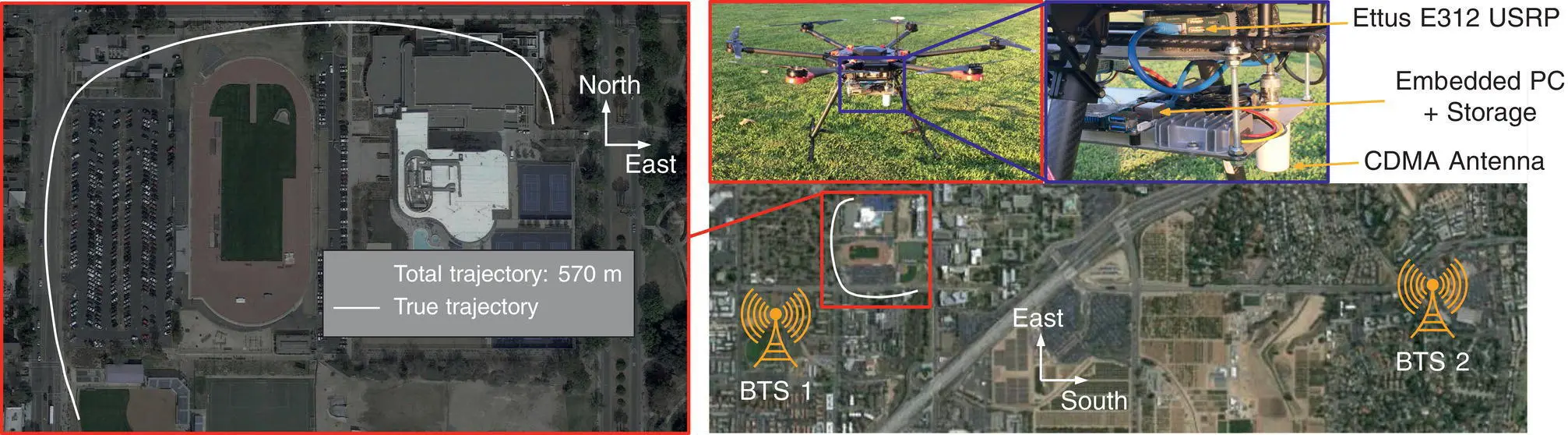
Figure 38.20 BTS environment and experimental hardware setup for the UAV experiment. Map data: Google Earth (Khalife et al. [12]).
Source: Reproduced with permission of IEEE.
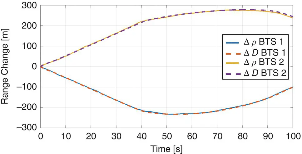
Figure 38.21 Variation in pseudoranges and the variation in distances between the receiver and two cellular CDMA BTSs for the UAV experiment (Khalife et al. [12]).
Source: Reproduced with permission of IEEE.
Ground Vehicle Results: Figure 38.22shows the BTS environment, ground vehicle trajectory, and the experimental hardware setup. Signals from two cellular BTSs corresponding to the US cellular provider Verizon Wireless were tracked. The BTSs transmitted at a carrier frequency of 882.75 MHz, and their positions were mapped prior to the experiment [37, 39]. The ground‐truth reference for the ground vehicle trajectory in Figure 38.22was obtained from the Generalized Radionavigation Interfusion Device (GRID) GPS SDR [58]. The change in the true range and the change in pseudorange are plotted in Figure 38.23, similarly to the UAV experiment. It can be seen from Figure 38.23that the variations in the pseudoranges closely follow the variations in distances. The difference between Δ D and Δ ρ for a particular BTS is due to the variation in the clock bias difference  and the noise v i.
38.5.4.2 Ground Vehicle Navigation
Two cars (mapper and navigator) were equipped with the cellular CDMA navigation receiver discussed in Section 38.5.2. The receivers were tuned to the cellular carrier frequency 882.75 MHz, which is a channel allocated to the US cellular provider Verizon Wireless. The mapper was stationary and was estimating the clock biases of the 3 BTSs via a WLS estimator as discussed in Section 38.4.1. The BTSs’ positions were known to the mapper, and the position states were expressed in a local 3D frame whose horizontal plane passes through the three BTSs and is centered at the mean of the BTSs’ positions. The height of the navigator was known and constant in the local 3D frame over the trajectory driven and was passed as a constant parameter to the estimator. Hence, only the navigator’s 2D position and its clock bias were estimated through the WNLS described in Section 38.4.1. The weights of the WNLS were calculated using Eq. (38.17)with  s. For the first pseudorange measurement, the WNLS iterations were initialized by setting the navigator’s initial horizontal position states at the origin of the 3D local frame and the initial clock bias to zero. For each subsequent pseudorange measurement, the WNLS iterations were initialized at the solution from the previous WNLS. The experimental hardware setup, the environment layout, and the true and estimated navigator trajectories are shown in Figure 38.24. The ground‐truth trajectory was obtained from the GRID GPS SDR [58]. It can be seen from Figure 38.24that the navigation solution obtained from the cellular CDMA signals closely follows the navigation solution obtained using GPS signals.

Figure 38.22 BTS environment, true trajectory, and experimental hardware setup for the ground vehicle experiment. Map data: Google Earth (Khalife et al. [12]).
Source: Reproduced with permission of IEEE.
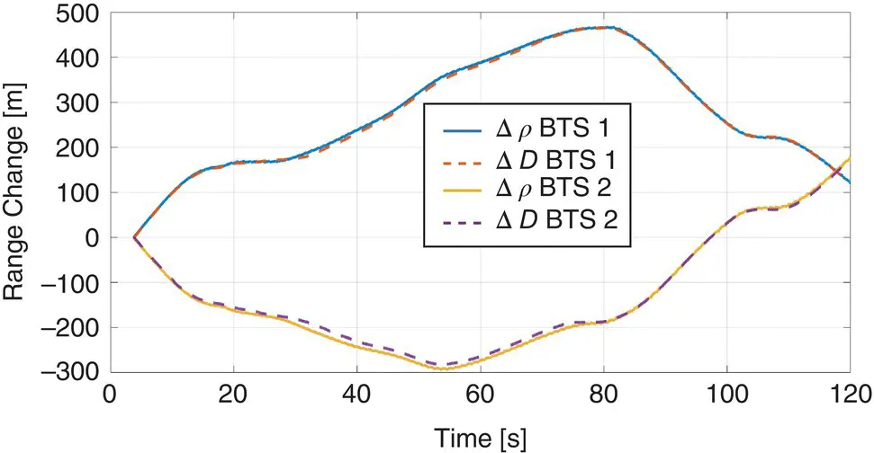
Figure 38.23 Variation in pseudoranges and the variation in distances between the receiver and two cellular CDMA BTSs for the ground vehicle experiment (Khalife et al. [12]).
Source: Reproduced with permission of IEEE.
38.5.4.3 Aerial Vehicle Navigation
Two identical UAVs (mapper and navigator) were equipped with the cellular CDMA navigation receiver discussed in Section 38.5.2. Here, both the mapper and navigator were mobile. The receivers were tuned to the cellular carrier frequency 882.75 MHz used by the US cellular provider Verizon Wireless. The mapper and navigator were listening to the same four BTSs with known positions. The mapper was estimating the BTSs’ clock biases via a WLS estimator as discussed in Section 38.4.1. Similar to the ground vehicle navigation setup, the height of the navigator was a known constant in the local 3D frame, and only the navigator’s 2D position and its clock bias were estimated through the WNLS, whose weights and initialization were calculated in a similar way as the ground vehicle navigation setup. The ground‐truth references for the mapper and navigator trajectories were taken from the UAVs’ onboard navigation systems, which use GPS, INS, and other sensors. Figure 38.25shows the BTS environment in which the mapper and navigator were present as well as the experimental hardware setup. The navigator’s true trajectory and estimated trajectory from cellular CDMA pseudoranges are shown in Figure 38.26.
38.6 Navigation with Cellular LTE Signals
Two different techniques can be employed to use LTE signals for PNT: network‐based and UE‐based. The network‐based technique was enabled in LTE Release 9 by introducing a broadcast positioning reference signal (PRS). The expected positioning accuracy with PRS is on the order of 50 m [59]. Network‐based positioning suffers from a number of drawbacks:
Читать дальшеИнтервал:
Закладка:
Похожие книги на «Position, Navigation, and Timing Technologies in the 21st Century»
Представляем Вашему вниманию похожие книги на «Position, Navigation, and Timing Technologies in the 21st Century» списком для выбора. Мы отобрали схожую по названию и смыслу литературу в надежде предоставить читателям больше вариантов отыскать новые, интересные, ещё непрочитанные произведения.


Обсуждение, отзывы о книге «Position, Navigation, and Timing Technologies in the 21st Century» и просто собственные мнения читателей. Оставьте ваши комментарии, напишите, что Вы думаете о произведении, его смысле или главных героях. Укажите что конкретно понравилось, а что нет, и почему Вы так считаете.