Point-of-Care Ultrasound Techniques for the Small Animal Practitioner
Здесь есть возможность читать онлайн «Point-of-Care Ultrasound Techniques for the Small Animal Practitioner» — ознакомительный отрывок электронной книги совершенно бесплатно, а после прочтения отрывка купить полную версию. В некоторых случаях можно слушать аудио, скачать через торрент в формате fb2 и присутствует краткое содержание. Жанр: unrecognised, на английском языке. Описание произведения, (предисловие) а так же отзывы посетителей доступны на портале библиотеки ЛибКат.
- Название:Point-of-Care Ultrasound Techniques for the Small Animal Practitioner
- Автор:
- Жанр:
- Год:неизвестен
- ISBN:нет данных
- Рейтинг книги:5 / 5. Голосов: 1
-
Избранное:Добавить в избранное
- Отзывы:
-
Ваша оценка:
Point-of-Care Ultrasound Techniques for the Small Animal Practitioner: краткое содержание, описание и аннотация
Предлагаем к чтению аннотацию, описание, краткое содержание или предисловие (зависит от того, что написал сам автор книги «Point-of-Care Ultrasound Techniques for the Small Animal Practitioner»). Если вы не нашли необходимую информацию о книге — напишите в комментариях, мы постараемся отыскать её.
New chapters in
cover ultrasound-guided nerve blocks, musculoskeletal, brain imaging, and applications of focused ultrasound techniques in cats, exotics and marine mammals—making it an essential purchase for veterinarians wanting to incorporate point-of-care ultrasound techniques into their veterinary practices.
Presents a standardized approach to point-of-care ultrasound as an extension of the physical exam, including trauma, non-trauma, and monitoring applications Includes coverage of new techniques for focused ultrasound exams, including lung, anesthesia and ultrasound guided nerve blocks, transcranial brain imaging, musculoskeletal, volume status evaluation, and rapid assessment for treatable forms of shock Adds cats, exotic and wildlife mammals, and marine mammals to the existing canine coverage Emphasizes the integration of point-of-care ultrasound techniques for optimizing patient care and accurate patient assessment Offers access to a companion website with supplementary video clips showing many clinically relevant didactic examples The second edition of
is an excellent resource for veterinary practitioners, ranging from the general practitioner to nearly all clinical specialists, including internal medicine, oncology, cardiology, emergency and critical care, anesthesiology, ophthalmology, exotics, and zoo medicine specialists, and veterinary students.
Point-of-Care Ultrasound Techniques for the Small Animal Practitioner — читать онлайн ознакомительный отрывок
Ниже представлен текст книги, разбитый по страницам. Система сохранения места последней прочитанной страницы, позволяет с удобством читать онлайн бесплатно книгу «Point-of-Care Ultrasound Techniques for the Small Animal Practitioner», без необходимости каждый раз заново искать на чём Вы остановились. Поставьте закладку, и сможете в любой момент перейти на страницу, на которой закончили чтение.
Интервал:
Закладка:
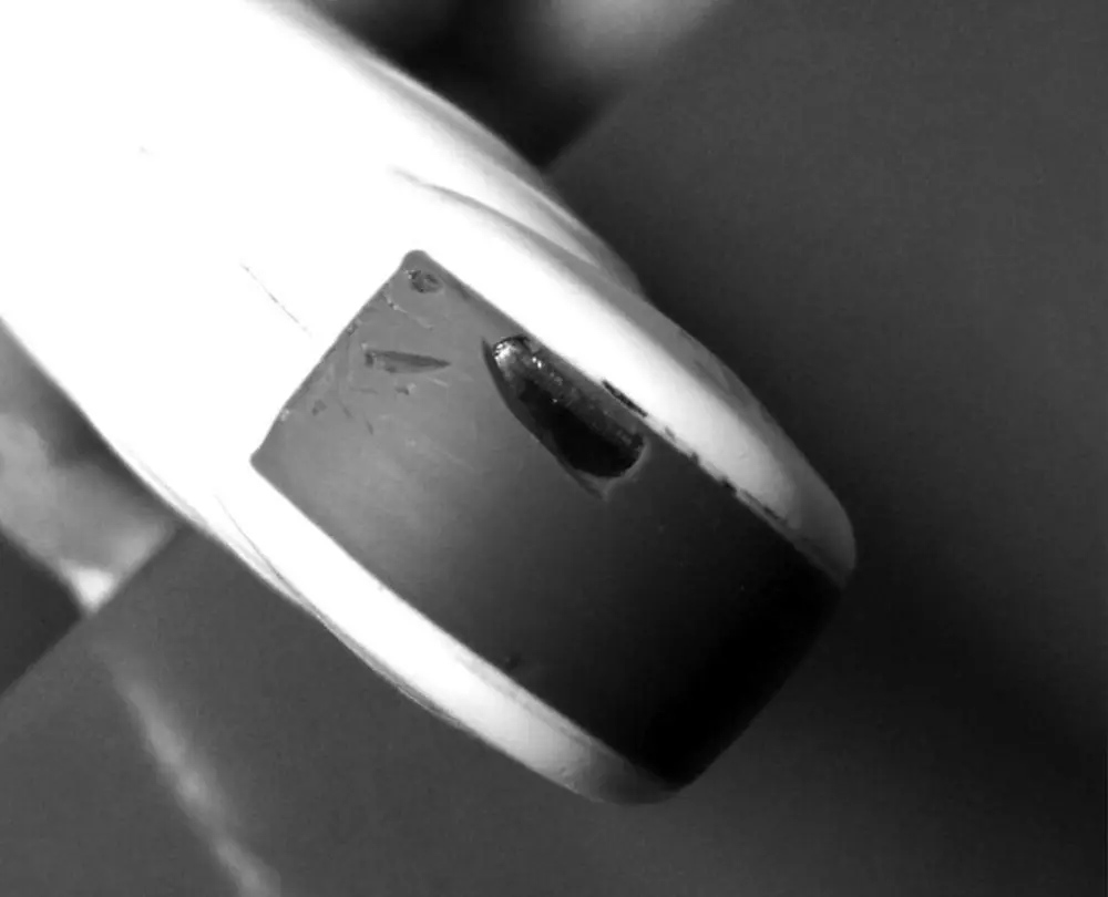
Figure 4.13. Probe head damage. The damage to the surface of this probe was attributed to a combination of repeated or prolonged contact with isopropyl alcohol and needle trauma. The contact layer is clearly lost over a portion of this probe, negating its ability to serve as an electrical insulator between the probe and patient. It is possible for potentially serious electric shock to occur through the damaged area.
Source: Courtesy of Robert M. Fulton, DVM, Richmond, VA.
Pearl:Always use acoustic coupling gel on the probe head and be familiar with the guidelines provided by the ultrasound machine's manufacturer.
Importantly, it should be noted that the rubber probe head accomplishes two things. First, it acts as a coupling medium to transmit the sound wave out of the probe. Second, it is part of an electrical insulator serving as an electrical ground between the patient and the electricity being sent from the ultrasound machine to the transducer's crystals. There are currently no reports of electrocution via a damaged ultrasound probe but theoretically it's possible.
Pearl:Avoid probe head damage by using an acoustic coupling medium on the probe head as a barrier to alcohol, and avoid stabbing the probe head with needles during ultrasound‐guided procedures.
Deciding on an Ultrasound Machine
Selecting the Machine
There are three main types of ultrasound machine: consoles, portables, and hand‐helds. The console machines are big and bulky, but they have stronger processors and thus give a better image. The portables, often laptop format, are easy to move to the exam table or cage side and their image quality is constantly improving. There are several small hand‐held machines now on the market. Some have adequate depth and resolution capabilities. Just make sure they don't “walk out of your clinic” or get tossed into the laundry or dropped or stepped on. It's very easy to put these hand‐held devices in a lab jacket pocket and forget about them.
You may be limited to whatever you currently have in your veterinary practice, but if you are thinking of buying a new unit, consider what your main use is going to be and get the best ultrasound machine you can afford for that purpose. The axiom holds true: the better the machine, the better the image, and hence the better the diagnostic information.
Selecting the Probe: Linear, Curvilinear, and Phased‐array
Probes, or transducers, come in two basic types, mechanical and electronic. Mechanical probes are on many counts considered outdated but there are still some around with their working parts visibly rotating or rocking under their translucent covers. Newer ultrasounds have electronic probes as standard. Electronic probes come in various arrangements. Probes are generally described by the size and shape of their face, referred to as their “footprint,” which is represented by the gray rubber probe covering (see Figure 4.13). Selecting the right probe is essential to getting good images, although there may be times when more than one probe may be appropriate for a given exam.
Three basic types of probes are used in general practice, emergency, and critical care POCUS: linear, curvilinear, and phased‐array (also known as sector) (see Figure 4.4). Linear probes are typically of higher frequency and have a rectangular footprint. Curvilinear probes are arranged along a convex face and are typically of lower frequency than linear probes. A phased‐array (sector) probe generates an image from an electronically steered beam in a close array, generating an image that comes from a point and is good for getting between ribs, such as in cardiac ultrasound. Both curvilinear and phased‐array probes generate sector or pie‐shaped images, narrow in the near‐field and wide in the far‐field. Phased‐array probes are typically lower frequency. Because of their smaller footprint, “pie‐shaped” image, and commonly used frequencies, curvilinear probes are generally the most versatile and ideal for POCUS and FAST studies.
Probes are generally named for the primary frequency they emit. For example, a General Electric (GE) 8C probe indicates that 8 MHz is its primary frequency and the C represents the probe’s curvilinear footprint. A GE 9L probe indicates a 9 MHz primary frequency in a linear (L) probe, and a GE 7S has 7 MHz as its primary frequency in a sector (S) probe. However, modern probes are capable of emitting a range of frequencies, known as bandwidth. In choosing the best frequency, we need to go back to basics. Remember that higher frequencies are attenuated more and that means less penetration but better detail. Lower frequencies are attenuated less and that means deeper penetration but less detail. Another rule of thumb is that the smaller the patient or area of interest, the higher the frequency (MHz) versus the larger the patient or area of interest, the lower the frequency (MHz).
Setting Up an Ultrasound Program
See Chapter 45for additional information.
Pearls and Pitfalls, The Final Say
In summary, these first four chapters have briefly covered some of the ultrasound basics. Other textbooks are available that go into more detail regarding ultrasound principles and artifacts, and many courses sponsored by ultrasound companies are available throughout the year to enhance learning. FASTVet.comis an online Global FAST education company. Another resource is the International Veterinary Point‐of‐Care Ultrasound Society's website www.IVPOCUS.org
It is important to be familiar with some of the basic principles, artifacts, and nuances associated with ultrasound as an imaging modality for your busy general practice, emergency room, or critical care unit to minimize misinterpretations. POCUS and FAST ultrasound are truly an “extension of the physical examination” and “the modern stethoscope” (Rozycki et al. 2001; Filly 1988).
So there you have it. Turn on your ultrasound machine, apply your coupling medium, and start scanning. Get POCUS and FAST and better pick your next test, more accurately treat, and better keep alive your patients for gold standard testing and treatment. POCUS and FAST save lives!
References
1 Bahner DP, Blickendorf JM, Bockbrader M, et al. 2016. Language of transducer manipulation. J Ultrasound Med 34:183–188.
2 Evans DH, McDicken WN, Skidmore R, Woodcock JP. 1989. Doppler Ultrasound: Physics, Instrumentation, and Clinical Applications. Chichester: Wiley.
3 Filly RA. Ultrasound: the stethoscope of the future, alas. Radiology 167:400.
4 Nyland TG, Mattoon JS, Herrgesell EJ, et al. 2002. Physical principles, instrumentation, and safety of diagnostic ultrasound. In: Small Animal Diagnostic Ultrasound, 2nd edition, edited by Nyland TG, Mattoon JS. Philadelphia: WB Saunders, pp 1–18.
5 Pozniak MA, Zagzebski JA, Scanlan KA. 1992. Spectral and color Doppler artifacts. Radiographics 12:35–44.
6 Rozycki GS, Pennington SD, Feliciano DV, et al. 2001. Surgeon‐performed ultrasound in the critical care setting: its use as an extension of the physical examination to detect pleural effusion. J Trauma 50:636–642.
Chapter Five POCUS: Top Ultrasound Mistakes During Global FAST
Gregory R. Lisciandro
Introduction
Having trained close to 1000 veterinarians from around the world in Global FAST, AFAST, TFAST, and Vet BLUE, we have come up with our top list for image acquisition and interpretation mistakes made during Global FAST that will help synthesize the previous three excellent chapters by Dr Fulton. Whichever machine you work with, you must understand its software, how it interprets artifacts, and what its strengths and weaknesses are to gain full confidence in its imaging potential. You also need to know how to optimize image acquisition by taking advantage of external patient features and the role your hands should play. This takes time, repetition, and critical thinking during image acquisition and a sonographer who dares to use the different buttons and controls on the machine.
Читать дальшеИнтервал:
Закладка:
Похожие книги на «Point-of-Care Ultrasound Techniques for the Small Animal Practitioner»
Представляем Вашему вниманию похожие книги на «Point-of-Care Ultrasound Techniques for the Small Animal Practitioner» списком для выбора. Мы отобрали схожую по названию и смыслу литературу в надежде предоставить читателям больше вариантов отыскать новые, интересные, ещё непрочитанные произведения.


Обсуждение, отзывы о книге «Point-of-Care Ultrasound Techniques for the Small Animal Practitioner» и просто собственные мнения читателей. Оставьте ваши комментарии, напишите, что Вы думаете о произведении, его смысле или главных героях. Укажите что конкретно понравилось, а что нет, и почему Вы так считаете.