James C. Kessler - Fundamentals of Fixed Prosthodontics
Здесь есть возможность читать онлайн «James C. Kessler - Fundamentals of Fixed Prosthodontics» — ознакомительный отрывок электронной книги совершенно бесплатно, а после прочтения отрывка купить полную версию. В некоторых случаях можно слушать аудио, скачать через торрент в формате fb2 и присутствует краткое содержание. Жанр: unrecognised, на английском языке. Описание произведения, (предисловие) а так же отзывы посетителей доступны на портале библиотеки ЛибКат.
- Название:Fundamentals of Fixed Prosthodontics
- Автор:
- Жанр:
- Год:неизвестен
- ISBN:нет данных
- Рейтинг книги:3 / 5. Голосов: 1
-
Избранное:Добавить в избранное
- Отзывы:
-
Ваша оценка:
Fundamentals of Fixed Prosthodontics: краткое содержание, описание и аннотация
Предлагаем к чтению аннотацию, описание, краткое содержание или предисловие (зависит от того, что написал сам автор книги «Fundamentals of Fixed Prosthodontics»). Если вы не нашли необходимую информацию о книге — напишите в комментариях, мы постараемся отыскать её.
Fundamentals of Fixed Prosthodontics — читать онлайн ознакомительный отрывок
Ниже представлен текст книги, разбитый по страницам. Система сохранения места последней прочитанной страницы, позволяет с удобством читать онлайн бесплатно книгу «Fundamentals of Fixed Prosthodontics», без необходимости каждый раз заново искать на чём Вы остановились. Поставьте закладку, и сможете в любой момент перейти на страницу, на которой закончили чтение.
Интервал:
Закладка:
Double abutments are sometimes used as a means of overcoming problems created by unfavorable crown-root ratios and long spans. There are several criteria that must be met if a secondary (remote from the edentulous space) abutment is to strengthen the fixed partial denture and not become a problem itself. A secondary abutment must have at least as much root surface area and as favorable a crownroot ratio as the primary (adjacent to the edentulous space) abutment it is intended to bolster. As an example, a canine can be used as a secondary abutment to a first premolar primary abutment, but it would be unwise to use a lateral incisor as a secondary abutment to a canine primary abutment. The retainers on secondary abutments must be at least as retentive as the retainers on the primary abutments. When the pontic flexes, tensile forces will be applied to the retainers on the secondary abutments ( Fig 7-19). There also must be sufficient crown length and space between adjacent abutments to prevent impingement on the gingiva under the connector.
Arch curvature has its effect on the stresses occurring in a fixed partial denture. When pontics lie outside the interabutment axis line, the pontics act as a lever arm, which can produce a torquing movement. This is a common problem in replacing all four maxillary incisors with a fixed partial denture, and it is most pronounced in the arch that is pointed in the anterior. Some measure must be taken to offset the torque. This can best be accomplished by gaining additional retention in the opposite direction from the lever arm and at a distance from the interabutment axis equal to the length of the lever arm 15( Fig 7-20). The first premolars sometimes are used as secondary abutments for a maxillary four-pontic canine-to-canine fixed partial denture. Because of the tensile forces that will be applied to the premolar retainers, they must have excellent retention.
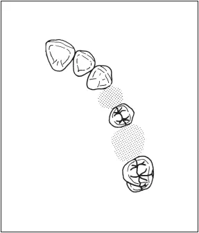
Fig 7-21In this frequently occurring situation, the maxillary first premolar and molar are missing, leaving the second premolar as a pier abutment.
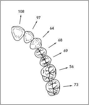
Fig 7-22The amount of faciolingual movement (in μm) for each tooth in the maxillary arch (based on data by Rudd et al16). The direction of movement, indicated by arrows, varies considerably from the anterior to the posterior segment of the arch.
Special Problems
Some problem situations occur often enough to deserve mention. Some of the commonly used solutions to the problems are also presented.
Pier abutments
Rigid connectors (eg, solder joints) between pontics and retainers are the preferred way of fabricating most fixed partial dentures. A fixed partial denture with the pontic rigidly fixed to the retainers provides desirable strength and stability to the prosthesis while minimizing the stresses associated with the restoration.
However, a completely rigid restoration is not indicated for all situations requiring a fixed prosthesis. An edentulous space can occur on both sides of a tooth, creating a lone, freestanding pier abutment ( Fig 7-21). Physiologic tooth movement, arch position of the abutments, and a disparity in the retentive capacity of the retainers can make a rigid fiveunit fixed partial denture a less-than-ideal treatment plan.
Studies in periodontometry have shown that the faciolingual movement ranges from 56 to 108 μm, 16and intrusion is 28 μm. 17Teeth in different segments of the arch move in different directions. 18Because of the curvature of the arch, the faciolingual movement of an anterior tooth occurs at a considerable angle to the faciolingual movement of a molar ( Fig 7-22).
These movements of measurable magnitude and in divergent directions can create stresses in a long-span prosthesis that will be transferred to the abutments. Because of the distance through which movement occurs, the independent direction and magnitude of movements of the abutment teeth, and the tendency of the prosthesis to flex, stress can be concentrated around the abutment teeth as well as between retainers and abutment preparations.
It has been theorized that forces are transmitted to the terminal retainers as a result of the middle abutment acting as a fulcrum, causing failure of the weaker retainer. 19However, photoelastic stress analysis and displacement measurement indicate that the prosthesis bends rather than rocks. Standlee and Caputo 20suggest that tension between the terminal retainers and their respective abutments, rather than a pier fulcrum, is the mechanism of failure. Intrusion of the abutments under the loading could lead to failure between any retainer and its respective abutment.
The loosened casting will leak around the margin, and caries is likely to become extensive before discovery. The retention on an anterior tooth is usually less than that of a posterior tooth because of its generally smaller dimensions. Because there are limits to increasing a retainer’s capacity to withstand displacing forces, some means must be used to neutralize the effects of those forces. The use of a nonrigid connector has been recommended to reduce this hazard. 19
In spite of an apparently close fit, the movement in a nonrigid connector is enough to prevent the transfer of stress from the segment being loaded to the rest of the fixed partial denture ( Fig 7-23). The nonrigid connector is a broken-stress mechanical union of retainer and pontic instead of the usual rigid connector. The most commonly used nonrigid design consists of a T-shaped key that is attached to the pontic and a dovetail keyway placed within a retainer.
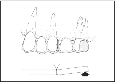
Fig 7-23A nonrigid connector on the middle abutment isolates force to the segment of the fixed partial denture to which it is applied. (Reprinted from Shillingburg and Fisher 19with permission.)
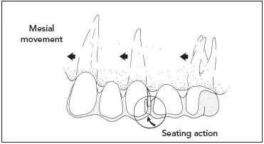
Fig 7-24If a nonrigid connector is placed on the distal side of the retainer on a middle abutment, movement in a mesial direction will seat the key into the keyway. (Reprinted from Shillingburg and Fisher 19with permission.)
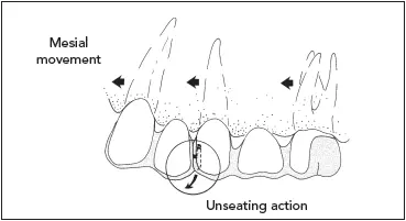
Fig 7-25If a nonrigid connector is placed on the mesial side of the middle abutment, mesially directed movement will unseat the key. (Reprinted from Shillingburg and Fisher 19with permission.)
Use of the nonrigid connector is restricted to a short-span fixed partial denture replacing one tooth. 21The magnification of force created by a long span is too destructive to the abutment tooth under the soldered retainer. Prostheses with nonrigid connectors should not be used if prospective abutment teeth exhibit significant mobility. There must be equal distribution of occlusal forces on all parts of the fixed partial denture.
A nonrigid fixed partial denture transfers shear stress to supporting bone rather than concentrating it in the connectors. It appears to minimize mesiodistal torquing of the abutments while permitting them to move independently. 22A rigid fixed partial denture distributes the load more evenly than a nonrigid design, making it preferable for teeth with decreased periodontal attachment. 23If the posterior abutment and pontic are either opposed by a removable partial denture or unopposed, and if the three anterior units are opposed by natural teeth, the key and the posterior units that are subjected to little or no occlusal forces may supererupt.
Читать дальшеИнтервал:
Закладка:
Похожие книги на «Fundamentals of Fixed Prosthodontics»
Представляем Вашему вниманию похожие книги на «Fundamentals of Fixed Prosthodontics» списком для выбора. Мы отобрали схожую по названию и смыслу литературу в надежде предоставить читателям больше вариантов отыскать новые, интересные, ещё непрочитанные произведения.


Обсуждение, отзывы о книге «Fundamentals of Fixed Prosthodontics» и просто собственные мнения читателей. Оставьте ваши комментарии, напишите, что Вы думаете о произведении, его смысле или главных героях. Укажите что конкретно понравилось, а что нет, и почему Вы так считаете.