Digital Workflow in Reconstructive Dentistry
Здесь есть возможность читать онлайн «Digital Workflow in Reconstructive Dentistry» — ознакомительный отрывок электронной книги совершенно бесплатно, а после прочтения отрывка купить полную версию. В некоторых случаях можно слушать аудио, скачать через торрент в формате fb2 и присутствует краткое содержание. Жанр: unrecognised, на английском языке. Описание произведения, (предисловие) а так же отзывы посетителей доступны на портале библиотеки ЛибКат.
- Название:Digital Workflow in Reconstructive Dentistry
- Автор:
- Жанр:
- Год:неизвестен
- ISBN:нет данных
- Рейтинг книги:4 / 5. Голосов: 1
-
Избранное:Добавить в избранное
- Отзывы:
-
Ваша оценка:
Digital Workflow in Reconstructive Dentistry: краткое содержание, описание и аннотация
Предлагаем к чтению аннотацию, описание, краткое содержание или предисловие (зависит от того, что написал сам автор книги «Digital Workflow in Reconstructive Dentistry»). Если вы не нашли необходимую информацию о книге — напишите в комментариях, мы постараемся отыскать её.
Contributors
Amirah M. R. Alammar • Abdulaziz Alsahaf • Wael Att • Maria Bateli • Jasmin Bernhart • Shaza Bishti • Sarah Blattner • Miha Brezavšček • Sandy Cepa • Nadine Emmanoulidi • Ahmed Fawzy • Manrique Fonseca • Michele Frapporti • Rumpa Ganguly • Yousef Al-Ghamdi • Petra Ch. Gierthmuehlen • Aiste Gintaute • Ulrich Lamott • Christos Lamprinos • Matthias Petsch • Udo Plaster • Aikaterini Ploumaki • Hanna Rauberger • Elisabeth Schwartzkopff • Christian F. Selz • Thamer Al-Sharif • Benedikt Spies • Frank A. Spitznagel • Jörg R. Strub • Michael Swain • Taskin Tuna • Alexander Vuck • Siegbert Witkowski
Digital Workflow in Reconstructive Dentistry — читать онлайн ознакомительный отрывок
Ниже представлен текст книги, разбитый по страницам. Система сохранения места последней прочитанной страницы, позволяет с удобством читать онлайн бесплатно книгу «Digital Workflow in Reconstructive Dentistry», без необходимости каждый раз заново искать на чём Вы остановились. Поставьте закладку, и сможете в любой момент перейти на страницу, на которой закончили чтение.
Интервал:
Закладка:
Currently available optical desktop scanners have vastly improved in all facets, such as speed, accuracy, and scanning capabilities. 3The software programs which are used to run these devices to generate and calculate the data are also constantly improving. This is noticeable in the decrease of the scanning and calculation times. A present system by 3Shape (D2000, released in 2016) is able to scan two casts and digitize the dies at a high resolution simultaneously ( Fig 3.1b).
However, three-dimensional (3D) scanning must generate a highly accurate, if not identical, digital reproduction of the surface topography of the object represented by a point cloud in a system of three spatial coordinates (by convention, x, y, and z). The number and accuracy of the measured points in the spatial space is responsible for the accuracy of the digital reproduction of the scanned surface. Multiple factors, such as the translucency of the object or its reflecting surface (related to the optical scan), the hardware of the scanner regarding its axis or the size of its tactile probe, and the calculating software, influence each scan and the accuracy of the result. Beside these factors, the time required for a single scan or multi-die model is economically significant ( Fig 3.1c).
Laser scanning and optical-stripe light projection represent optical measurement technologies primarily deployed for the 3D digitization of the surface of a dental cast or impression. They are both based on the same principle of triangulation; light structures (usually stripes) are projected onto the object, and light sensors acquire the image; using values from the known geometry of the setup, 3D information can be calculated from the imaged data.
The difference between the two methods resides in the way the light structure is projected and imaged. In laser scanning, laser light sources are used to project one or multiple thin, sharp stripes onto the scanned object; in optical-stripe light projection systems, light patterns (usually in the form of a bundle of stripes) are projected onto the entire object being scanned. While laser scanners were previously considered to provide higher resolution and accuracy, both methods today offer a precision of 10 μm or less. 3The spectrum of applications for current desktop scanners varies from scans of individual dies to scans of arch segments, complete arch casts, impressions, bite records, and wax-ups. To improve scan accuracy, some scanners require the application of a nonreflecting agent, while others require the use of casts made of scan-compatible gypsum. Newly introduced scanners include high-resolution cameras that allow for adaptive impression scanning, as well as texture-capture capabilities and surface coloring ( Figs 3.2and 3.3).
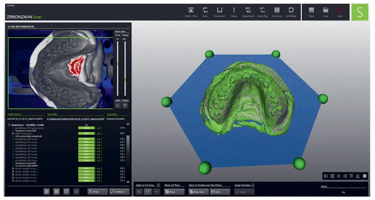
Fig 3.2Scan of a conventional dental impression.
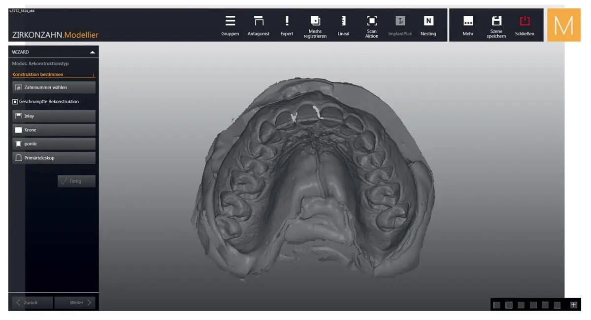
Fig 3.3Image of a scanned dental impression.
Usually, the scanner features at least two capture devices (two cameras or two laser sensors) while the holder for the model (object to be scanned) is attached to a multiple axis rotation mechanism, allowing the object to be rotated and tilted during the scanning process. This motion feature enables the capture devices to effectively detect the object from any viewpoint; scan all details of the object, including undercuts; increase the size of the measuring field; and improve the overall accuracy of the scan data. Recently introduced desktop scanners can scan two models at the same time and do not require an extra scanning process for the acquisition of the prepared dies, provided there is full optical access of the projected light to the object ( Fig 3.4a).
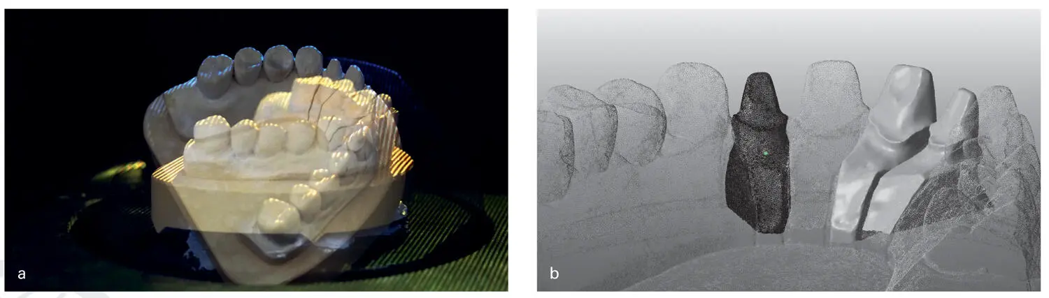
Fig 3.4(a) The object (model) is scanned in different positions. The object can be rotated and tilted on the holder while the light is projected. (b) The digital working model contains information from multiple scans. The individual files are differentially visualized after meshing to indicate this.
Software and Workflow
Acquisition and Processing of Scan Data
The developed point clouds produced by 3D scanners and their integrated software represent the digital conversion of the physical geometrical surface. The analog data of the surface is converted into digital data by image processing. 4These point clouds are stored in one or more files, mostly in proprietary (closed) formats prepared for the next data processing step of providing a unencrypted (open) file that can be transferred to the design software. In this data processing step, the software cleans and filters the points of the acquisition process, which can contain aberrant and highly concentrated points due to multiple, overlapping scan procedures. Software algorithms then clean and align the points of the captured physical surface. This is a critical phase and can lead to divergences from the reality of the teeth and soft tissue. The developed point cloud can be compiled by multiple scans at several resolutions. Thus, it is possible to rescan and exchange single data files, such as dies with high resolution or neighboring teeth with less concentrated points. Advanced systems also allow the cut-out of areas of the point cloud and enable a rescan and insert of the new situation.
This process produces a single file containing a list of the individual clouds and the coordinates to relate them to each other. In scan systems with an open-format output, the data can be transferred and interpreted by the following post-processing and design utilizing the unencrypted data. These data can be used directly for measurement and visualization in the design (CAD) and later in the production (CAM) processes ( Table 3.1).
Table 3.1Data acquisition and processing steps in the digital workflow to generate a data file for the design process
| Step | Action | Digital result and output |
| Acquisition | Scanning of surface with hardware | Virtual discrete geometrical data of multiple scans with multiple clouds |
| Processing | Software algorithms for treating point clouds | Virtual discrete geometrical data with one cloud |
| Post-processing | Software algorithms for meshing point clouds | Virtual continuous data with a CAD model |
While working in the data acquisition process, and later in the design modus, the operator does not visualize the point cloud, but rather a closed and connected surface between the points, on the screen. This surface does not provide the possibility to evaluate the distribution of the points. Measurement errors, such as holes caused by missing points, can be closed by the calculation process of the software. Thus, the scan holes – up to a preset degree – are automatically closed and therefore invisible to the user. The same phenomenon is present at the sharp edges and corners of a surface. To reproduce these fine surface characteristics of the object, it is necessary to have a very fine and precise distribution of the points and a customized algorithm for dental application in the processing phase of the point cloud. Thus, the accuracy of the scan and developed cloud depends on the hardware in combination with a system and dentistry-specific software.
Post-processing of Scan Data for CAD
The processed digitized data from the scan software is then transferred to the CAD software. Prior to the design phase, the digital geometrical data must be converted (post-processing) into a virtual representation with continuous geometrical data. 4This will provide a visualization of the scan data in one piece with a solid surface to commence the design process within the CAD software ( Fig 3.4b).
Читать дальшеИнтервал:
Закладка:
Похожие книги на «Digital Workflow in Reconstructive Dentistry»
Представляем Вашему вниманию похожие книги на «Digital Workflow in Reconstructive Dentistry» списком для выбора. Мы отобрали схожую по названию и смыслу литературу в надежде предоставить читателям больше вариантов отыскать новые, интересные, ещё непрочитанные произведения.


Обсуждение, отзывы о книге «Digital Workflow in Reconstructive Dentistry» и просто собственные мнения читателей. Оставьте ваши комментарии, напишите, что Вы думаете о произведении, его смысле или главных героях. Укажите что конкретно понравилось, а что нет, и почему Вы так считаете.