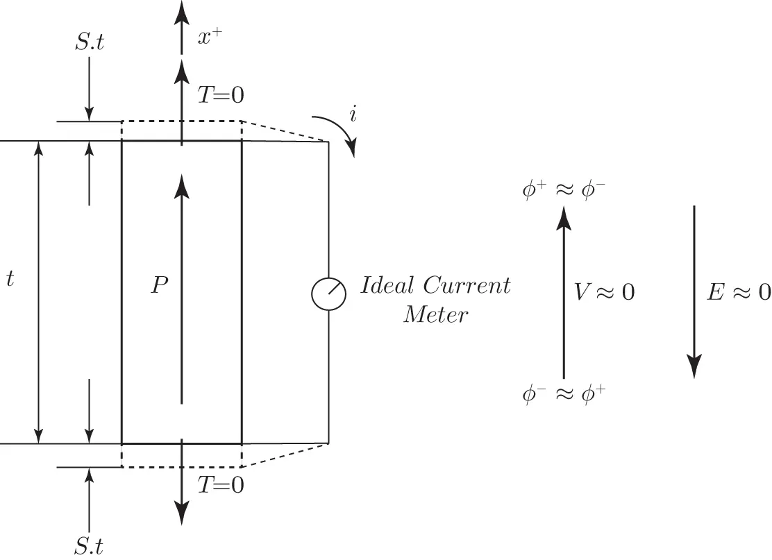
where  is the mechanical compliance constant,
  is the piezoelectric coupling constant, and
  is the permittivity constant. See Chapter 5for a precise definition of these constants when interpreted as elements of tensors suitable for piezoelectric continua in three dimensions. Since the current meter is ideal, the electrical potential
  at the top electrode is equal to the potential at the bottom electrode, and the electric field
  . From Equation 1.1it follows that the strain
  is positive, and the top and bottoms of the specimens displace by approximately
  , and the specimen stretches by a total amount
  . The magnitude of the charge on the electrodes can be obtained from the boundary conditions
  . Thus, we see that either the application of a positive stress
  , or equivalently of a positive strain
  , induces charges having magnitude
  on the faces of the specimen.
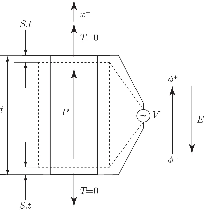
In contrast, Figure 1.6illustrates how the application of an electric potential across a piezoelectric specimen generates a deformation. In this case, we assume that the potential at the top electrode is  , the potential at the lower electrode is
  , and the voltage source has a voltage
  . Since the stress
  and
and  , the electrical field
  is approximately given by
  , and the strain in the specimen at its top and bottom is
  . In this case, the specimen compresses in total approximately by
  .
.

Figure 1.5 The direct piezoelectric effect.

Figure 1.6 The converse piezoelectric effect.
While the earliest applications of the piezoelectric effect were mostly related to ultrasound generation or sound measurements, the commercially viable applications of piezoelectricity have grown remarkably in diversity since that time. A quick survey of companies such as PCB® or PI Ceramics® that offer a broad range of piezoelectric devices can quickly convey the breadth of applications. For example, PI Ceramics notes that a piezoelectric device finds use in “… high‐end technology markets, such as medical technology, mechanical and automotive engineering or semiconductor technology, but is also present in everyday life, for example as a generator of ultrasonic vibrations in a cleaning bath for glasses and jewelry or in medical tooth cleaning .” The companies PCB® [36] and PI Ceramics® [37] include descriptions of broad applications areas. Even within each of these areas, the specific inventory of applications can be vast. Accelerometers, for example, are but one specific class of piezoelectrically‐based sensor that are used to measure vibration, shock, and acceleration for testing, control, online estimation, and system monitoring. The company PCB® [36] notes on http://www.pcb.com/TestMeasurement/Accelerometersthat their products in this niche of sensors support applications in “ …balancing, bearing, analysis, biomechanics, building vibration monitoring, biomechanics, bridge monitoring, component durability testing, crash testing, drop testing, fatigue testing, gearbox monitoring, environmental testing, ground vibration testing, impact measurements, impulse response measurements, machinery vibration, modal analysis, package testing, product qualification, quality control, seismic monitoring, structural testing, structure‐borne noise, vibration analysis, vibration isolation, and vibration stress screening.”
Despite the growth of the applications of piezoelectric technology catalogued above, it is common that they are often grouped into three general categories: energy applications, sensors, and actuators or motors. We discuss these next.
1.2.1 Energy Applications
While small piezoelectric specimens typically to do not output large currents or power, they can generate very high voltage differences under application of stress. It is for this reason that piezoelectric igniters are commonly used in gas broilers, gas stoves and ranges, gas fireplaces, or other appliances. The igniters usually operate by releasing a spring loaded switch that impacts the piezoelectric specimen, thereby generating a large, transient potential difference [36]. Such a voltage is high enough that it induces current flow across a gap that ignites the gas. In addition, the use of piezoelectric transducers in energy harvesting applications is a rapidly growing field. See for example [14] and the references therein for a good, comprehensive technical treatment of this topic. As noted before, while small piezoelectric transducers usually are not appropriate as large supplies of power, they are well suited to applications that require local, modular, or isolated energy sources for microscale electromechanical (MEMs) devices. Often, classes of sensors require small sources of energy to perform their associated measurements, and piezoelectric transducers have proven to be a viable route to support such sensors. There are numerous studies of energy reclamation from a wide range of sources [14]. Examples of composite piezoelectric structures that are connected to linear, ideal, passive electrical networks are studied in Chapters 6, 7, and 8. These electromechanical models are also suitable for the study of nonlinear switching strategies for energy harvesting. The emerging field of MEMs or NEMs (nanoelectromechanical systems) robotics requires microscale energy supplies to enable their mobility, and piezoelectric transducers are often the choice to develop self‐contained MEMs robots.
Читать дальше

 is the mechanical compliance constant,
  is the piezoelectric coupling constant, and
  is the permittivity constant. See Chapter 5for a precise definition of these constants when interpreted as elements of tensors suitable for piezoelectric continua in three dimensions. Since the current meter is ideal, the electrical potential
  at the top electrode is equal to the potential at the bottom electrode, and the electric field
  . From Equation 1.1it follows that the strain
  is positive, and the top and bottoms of the specimens displace by approximately
  , and the specimen stretches by a total amount
  . The magnitude of the charge on the electrodes can be obtained from the boundary conditions
  . Thus, we see that either the application of a positive stress
  , or equivalently of a positive strain
  , induces charges having magnitude
  on the faces of the specimen.
 , the potential at the lower electrode is
  , and the voltage source has a voltage
  . Since the stress
  and
and  , the electrical field
  is approximately given by
  , and the strain in the specimen at its top and bottom is
  . In this case, the specimen compresses in total approximately by
  .
.


