Interpretation Basics of Cone Beam Computed Tomography
Здесь есть возможность читать онлайн «Interpretation Basics of Cone Beam Computed Tomography» — ознакомительный отрывок электронной книги совершенно бесплатно, а после прочтения отрывка купить полную версию. В некоторых случаях можно слушать аудио, скачать через торрент в формате fb2 и присутствует краткое содержание. Жанр: unrecognised, на английском языке. Описание произведения, (предисловие) а так же отзывы посетителей доступны на портале библиотеки ЛибКат.
- Название:Interpretation Basics of Cone Beam Computed Tomography
- Автор:
- Жанр:
- Год:неизвестен
- ISBN:нет данных
- Рейтинг книги:4 / 5. Голосов: 1
-
Избранное:Добавить в избранное
- Отзывы:
-
Ваша оценка:
Interpretation Basics of Cone Beam Computed Tomography: краткое содержание, описание и аннотация
Предлагаем к чтению аннотацию, описание, краткое содержание или предисловие (зависит от того, что написал сам автор книги «Interpretation Basics of Cone Beam Computed Tomography»). Если вы не нашли необходимую информацию о книге — напишите в комментариях, мы постараемся отыскать её.
Enables rapid reference to common CBCT findings, with multiple images for each finding Features a streamlined framework that makes relevant information easier to find and apply in dental practice Offers hundreds of new images to aid in correctly identifying findings Contains new and updated content, including expanded coverage of CBCT and implants Provides sample reports and explains how they are used in day-to-day clinical practice
remains a must-have resource for all dental practitioner and specialists who use CBCT, dental students in radiology interpretation courses, and residents beginning to use CBCT in their specialty.
Interpretation Basics of Cone Beam Computed Tomography — читать онлайн ознакомительный отрывок
Ниже представлен текст книги, разбитый по страницам. Система сохранения места последней прочитанной страницы, позволяет с удобством читать онлайн бесплатно книгу «Interpretation Basics of Cone Beam Computed Tomography», без необходимости каждый раз заново искать на чём Вы остановились. Поставьте закладку, и сможете в любой момент перейти на страницу, на которой закончили чтение.
Интервал:
Закладка:
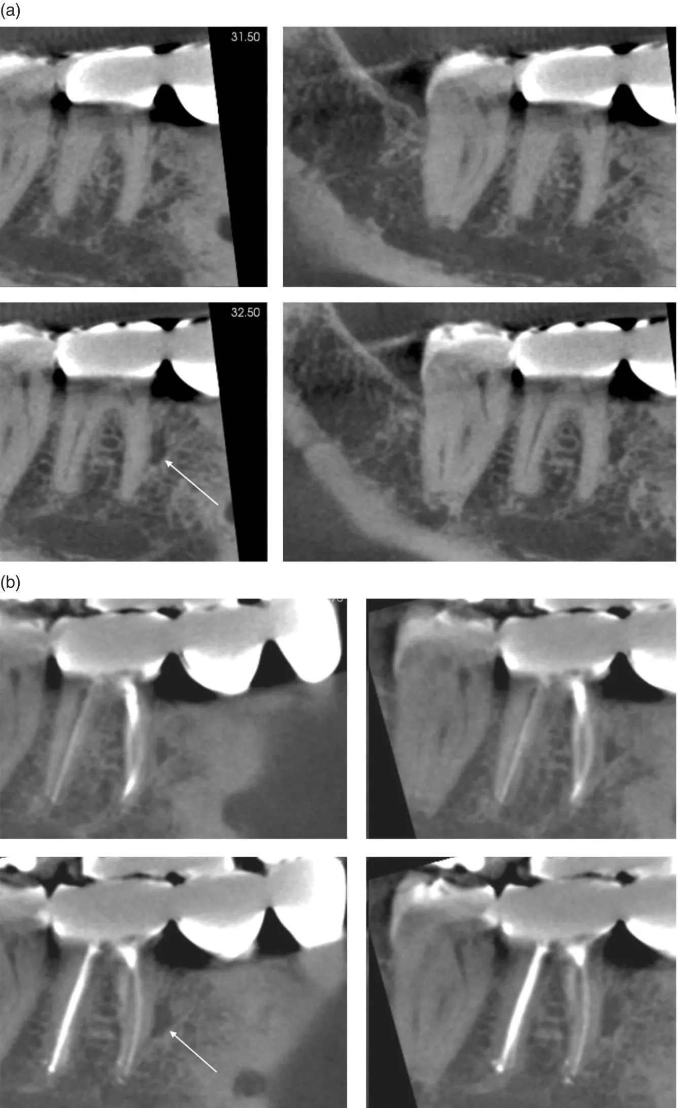
Figure 2.9. (a) Rotated sagittal views showing a bone defect (white arrow) on the mesial of a mandibular molar. (b) Rotated sagittal views showing a bone defect (white arrow) on the mesial of a mandibular molar captured 6 months after (a) suggestive of a prominent marrow space.
Orthodontics
The AAOMR published a paper in 2013 with recommendations regarding CBCT use in orthodontics. There are four main guidelines given.
1 = Image appropriately according to the patient’s clinical condition.
Imaging should be based on a patient’s history, clinical examination, and presence of clinical findings where CBCT benefits outweigh risks. Avoid using a CBCT only for lateral cephalometric and panoramic views or when information can be obtained with nonionizing methods such as virtual models. When using CBCT, a FOV that captures only the region of interest should be used.
2 = Assess the radiation dose risk.
Consider the relative radiation level when assessing imaging risk over the course of orthodontic treatment. Explain risks and benefits to patients prior to imaging and document in patients records.
3 = Minimize patient radiation exposure.
Take a CBCT with proper settings, a FOV that matches the region of interest, adult versus child setting, and appropriate voxel size. Use shielding when possible, but make sure that it is not captured in the FOV ( Figure 2.10). If you have a CBCT unit in office, ensure the machine is continually calibrated.
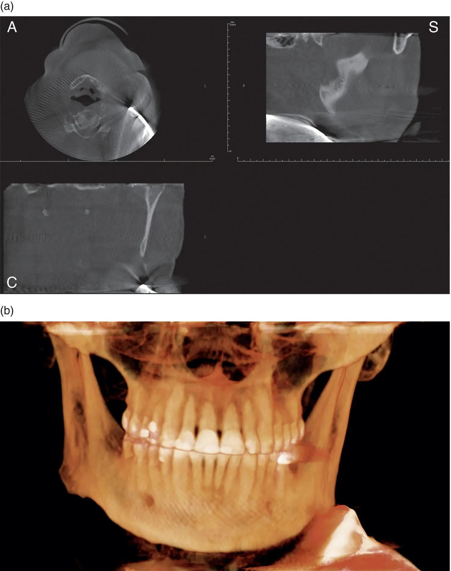
Figure 2.10. (a) Axial (A), coronal (C), and sagittal (S) views showing a thyroid collar captured in the FOV. (b) 3D reconstruction showing a thyroid collar captured in the FOV.
4 = Maintain professional competency in performing and interpreting CBCT studies.
Practitioners should continually attend continuing education (CE) courses, staying informed of the latest CBCT information. Practitioners have a legal responsibility to comply with local laws regarding CBCT use and interpretation. Patients should be informed of CBCT limitations (not a soft‐tissue imaging modality, artifacts, etc.).
Specific Orthodontic Uses
In 2015, Fisher recommended a list of case types for CBCT imaging in orthodontics.
1 = Impacted canines.
The most commonly impacted teeth are third molars and maxillary canines. CBCT imaging provides exact locations of impacted canines and the presence or absence of external root resorption of adjacent teeth ( Figures 2.11and 2.12). Cross‐sectional views are recommended to determine exact facial‐lingual width and effect on adjacent teeth. The FOV recommended is large enough to capture the tooth or teeth in question and surrounding bone and anatomical structures. The recommended voxel size is 0.3 mm to reduce the overall radiation exposure.
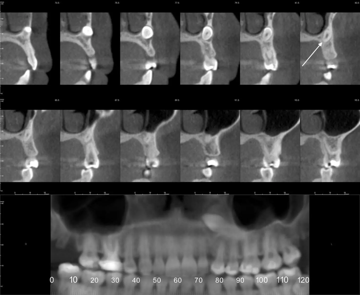
Figure 2.11. Reconstructed pantomograph and cross‐sectional slices showing location of an impacted maxillary canine (white arrow).
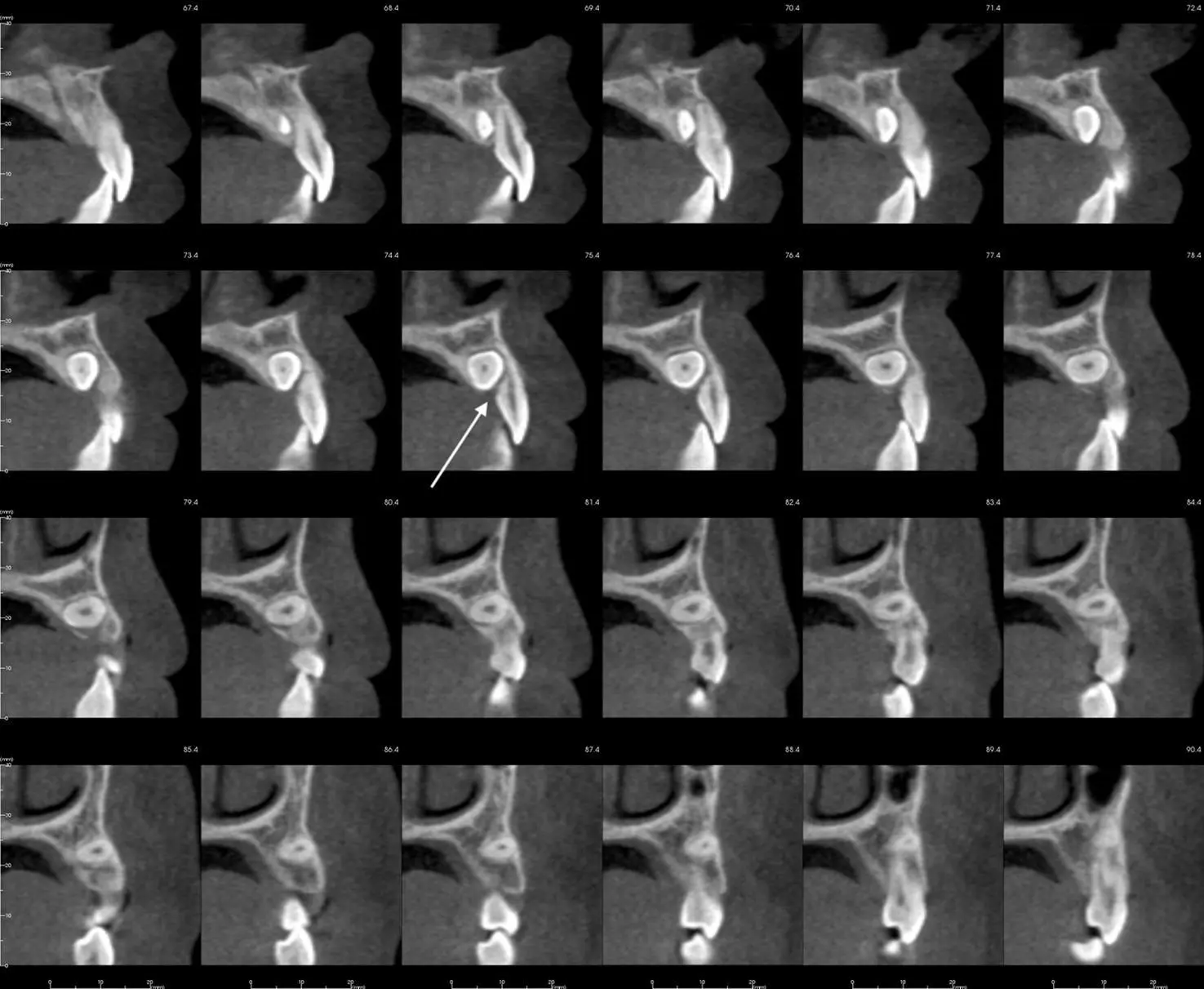
Figure 2.12. Cross‐sectional slices of an impacted maxillary canine with external resorption on the lingual aspect of the lateral incisor (white arrow).
2 = Orthognavthic surgery.
CBCT imaging has shown limited research that scans are reliable when determining the bony dimensions of a cleft palate ( Figure 2.13). Cleft palate cases are recommended for CBCT imaging, as 2D radiographs cannot show facial‐lingual dimensions of a defect. This additional information is helpful to a surgeon especially prior to bone grafting and helpful to an orthodontist prior to movement of teeth near the defect. Axial views are recommended to determine the bone quantity surrounding roots of teeth adjacent to the cleft. The FOV recommended is large enough to see the entire cleft and portions of the nasal cavity for the surgeon to have all of the information necessary. The recommended voxel size is 0.3 mm or larger, so as to reduce the overall radiation exposure.
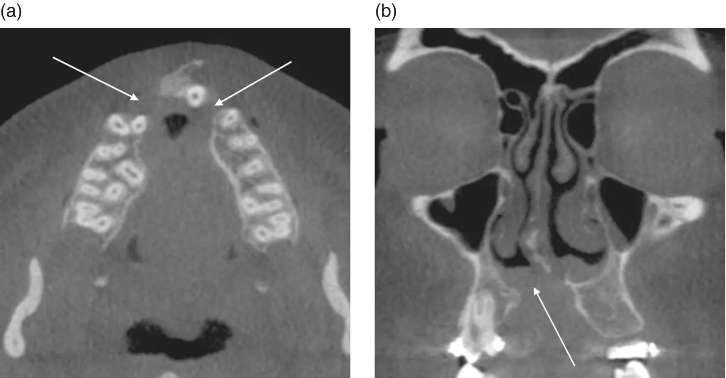
Figure 2.13. (a) Axial view showing a bilateral cleft palate (white arrows). (b) Coronal view showing a discontinuity of the floor of the right nasal cavity associated with a cleft palate (white arrow).
3 = Any patient needing anterior teeth moved in the sagittal plane.
4 = Temporary anchorage devices.
5 = Maxillary expansion.
6 = Permanent implant (see Chapter 11for more information).
7 = Compromised airway.
8 = Temporomandibular joint disorder (TMD) (see Chapter 10for more information).
9 = Supernumerary teeth ( Figure 2.14).
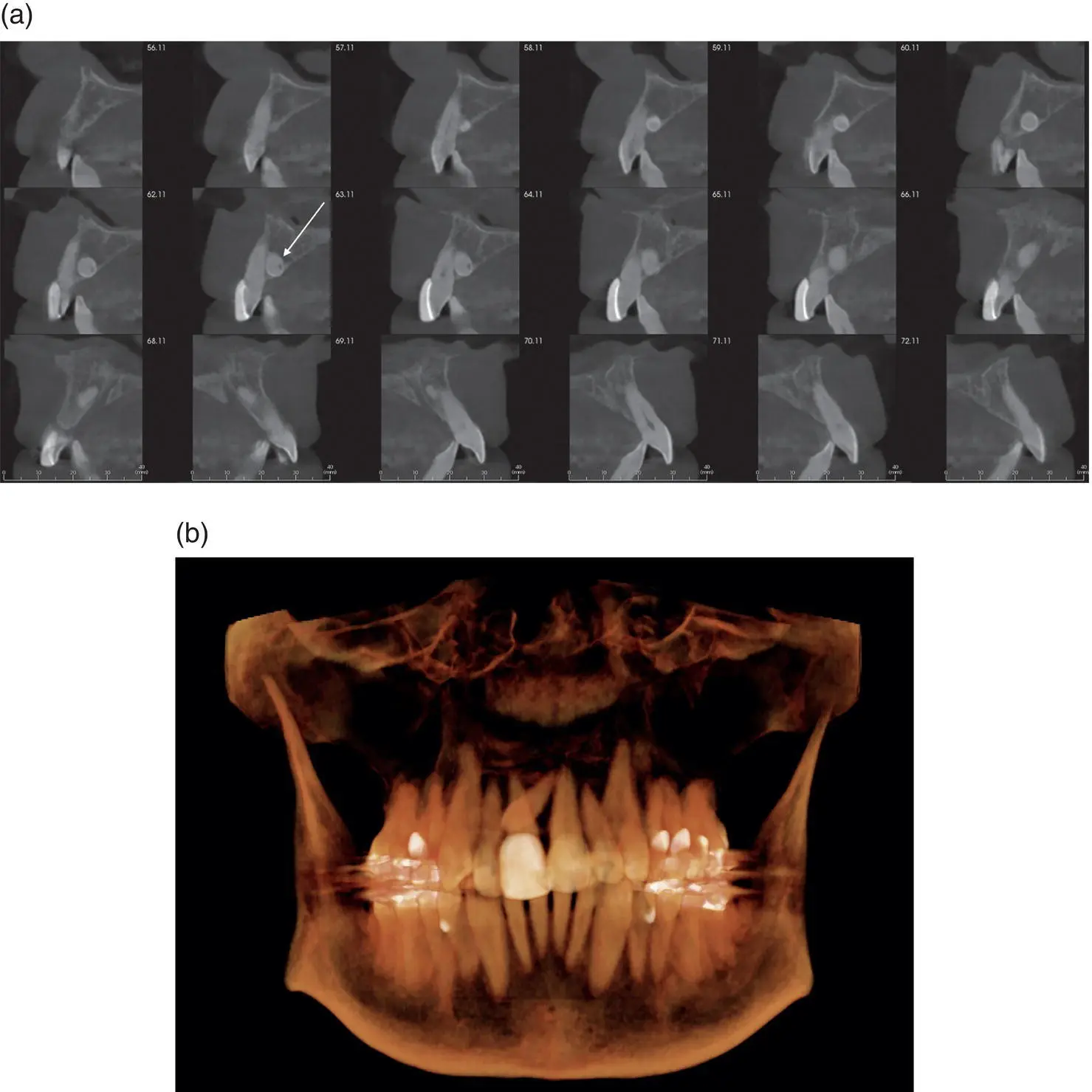
Figure 2.14. (a) Cross‐sectional slices showing a supernumerary tooth position (white arrow) in relation to the erupted maxillary incisors. (b) 3D reconstruction showing a supernumerary tooth horizontally positioned.
10 = Pathology.
There are various bony lesions that present throughout the jaws ( Figures 2.15and 2.16). CBCT imaging provides additional information about the exact location and possible nature of a bony lesion prior to removal or biopsy. All views (axial, coronal, sagittal, and cross‐sectional) are recommended to completely grasp the size, position, and nature of a lesion. The FOV recommended is one large enough to capture the area in question. The recommended voxel size is 0.3 mm to reduce the overall radiation exposure.
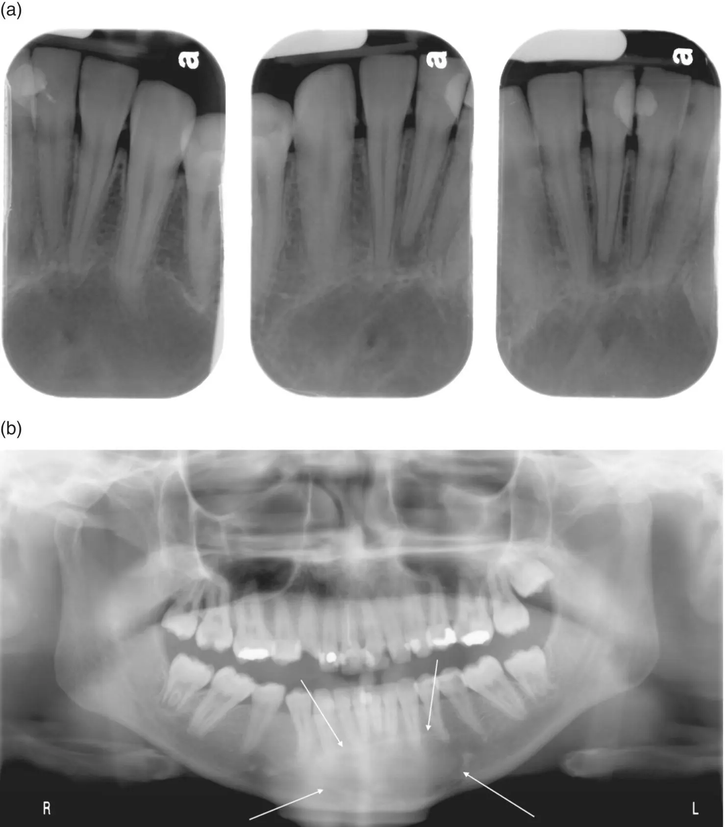
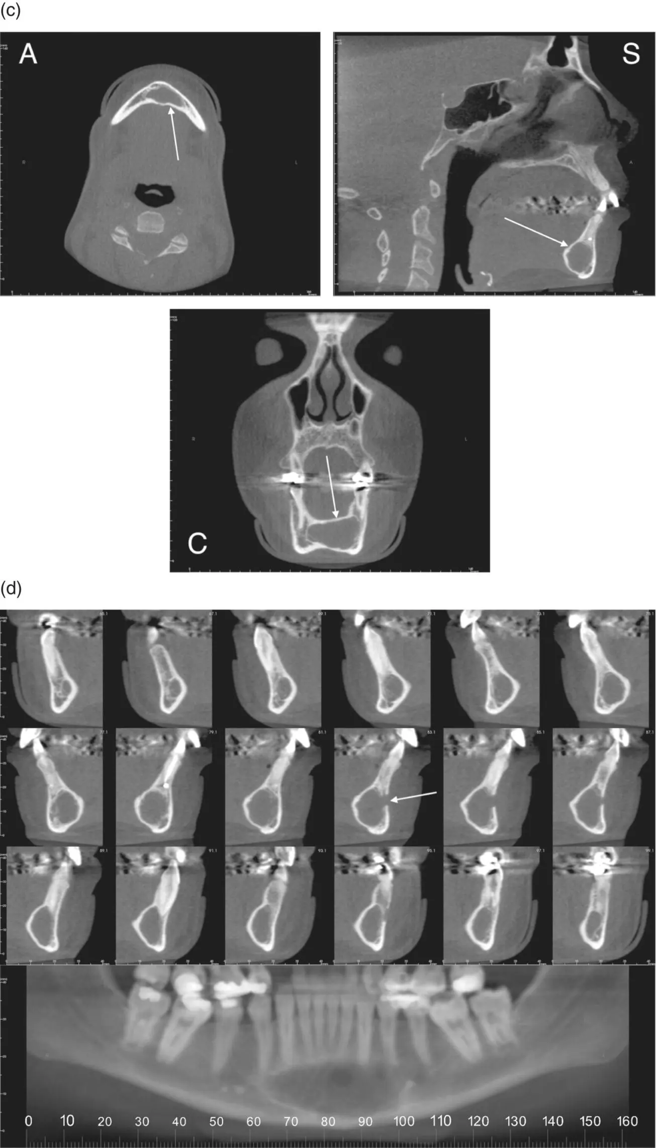
Figure 2.15. (a) Periapical radiographs showing a well‐defined, corticated radiolucent area inferior to the apices of the mandibular incisors confirmed as an odontogenic myxoma histopathologically. (b) Pantomograph showing a well‐defined radiolucent area in the anterior mandible (white arrows) confirmed as an odontogenic myxoma histopathologically.
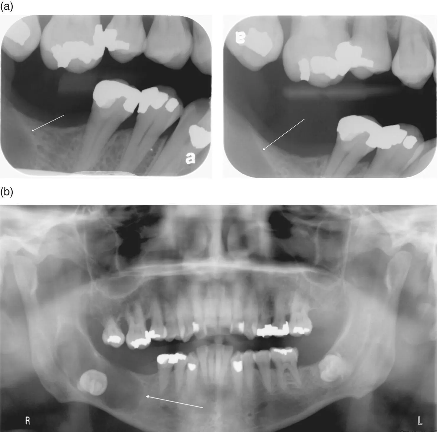
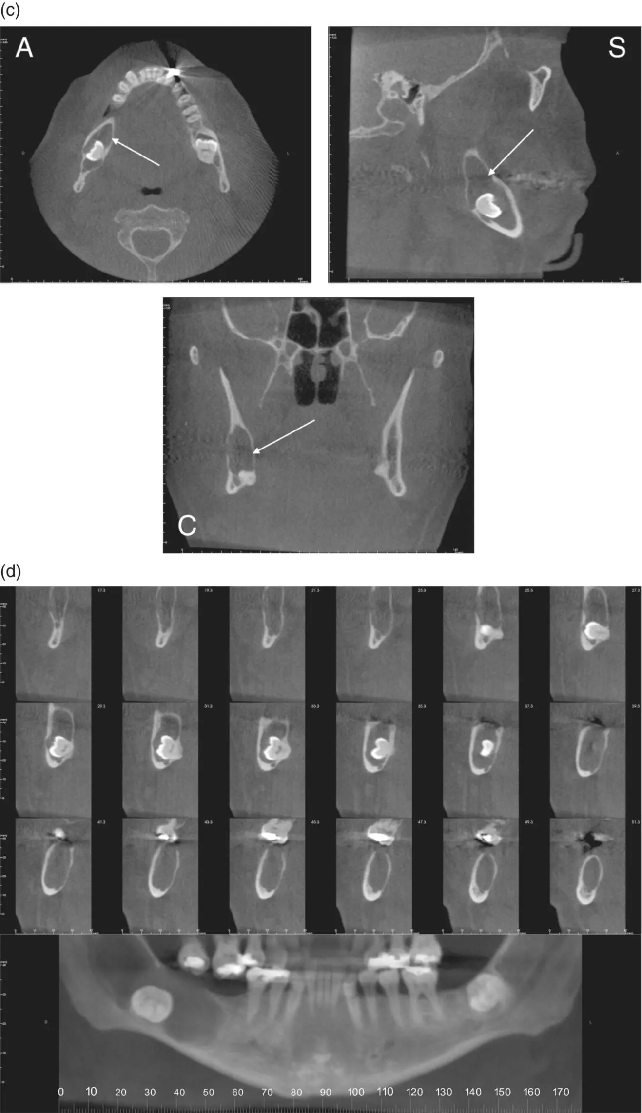
Figure 2.16. (a) Bitewing radiographs showing bone loss (white arrow) in the mandible. (b) Pantomograph showing a well‐defined, corticated, ovoid radiolucent area around an impacted mandibular right third molar (white arrow) consistent with a dentigerous cyst.
Читать дальшеИнтервал:
Закладка:
Похожие книги на «Interpretation Basics of Cone Beam Computed Tomography»
Представляем Вашему вниманию похожие книги на «Interpretation Basics of Cone Beam Computed Tomography» списком для выбора. Мы отобрали схожую по названию и смыслу литературу в надежде предоставить читателям больше вариантов отыскать новые, интересные, ещё непрочитанные произведения.


Обсуждение, отзывы о книге «Interpretation Basics of Cone Beam Computed Tomography» и просто собственные мнения читателей. Оставьте ваши комментарии, напишите, что Вы думаете о произведении, его смысле или главных героях. Укажите что конкретно понравилось, а что нет, и почему Вы так считаете.