Interpretation Basics of Cone Beam Computed Tomography
Здесь есть возможность читать онлайн «Interpretation Basics of Cone Beam Computed Tomography» — ознакомительный отрывок электронной книги совершенно бесплатно, а после прочтения отрывка купить полную версию. В некоторых случаях можно слушать аудио, скачать через торрент в формате fb2 и присутствует краткое содержание. Жанр: unrecognised, на английском языке. Описание произведения, (предисловие) а так же отзывы посетителей доступны на портале библиотеки ЛибКат.
- Название:Interpretation Basics of Cone Beam Computed Tomography
- Автор:
- Жанр:
- Год:неизвестен
- ISBN:нет данных
- Рейтинг книги:4 / 5. Голосов: 1
-
Избранное:Добавить в избранное
- Отзывы:
-
Ваша оценка:
Interpretation Basics of Cone Beam Computed Tomography: краткое содержание, описание и аннотация
Предлагаем к чтению аннотацию, описание, краткое содержание или предисловие (зависит от того, что написал сам автор книги «Interpretation Basics of Cone Beam Computed Tomography»). Если вы не нашли необходимую информацию о книге — напишите в комментариях, мы постараемся отыскать её.
Enables rapid reference to common CBCT findings, with multiple images for each finding Features a streamlined framework that makes relevant information easier to find and apply in dental practice Offers hundreds of new images to aid in correctly identifying findings Contains new and updated content, including expanded coverage of CBCT and implants Provides sample reports and explains how they are used in day-to-day clinical practice
remains a must-have resource for all dental practitioner and specialists who use CBCT, dental students in radiology interpretation courses, and residents beginning to use CBCT in their specialty.
Interpretation Basics of Cone Beam Computed Tomography — читать онлайн ознакомительный отрывок
Ниже представлен текст книги, разбитый по страницам. Система сохранения места последней прочитанной страницы, позволяет с удобством читать онлайн бесплатно книгу «Interpretation Basics of Cone Beam Computed Tomography», без необходимости каждый раз заново искать на чём Вы остановились. Поставьте закладку, и сможете в любой момент перейти на страницу, на которой закончили чтение.
Интервал:
Закладка:
Figure 1.7. Axial (A), coronal (C), sagittal (S), and reconstructed 3D views.
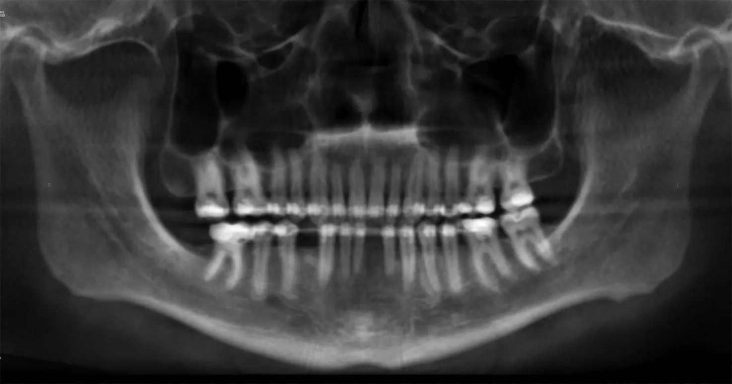
Figure 1.8. Reconstructed pantomograph from a CBCT scan.
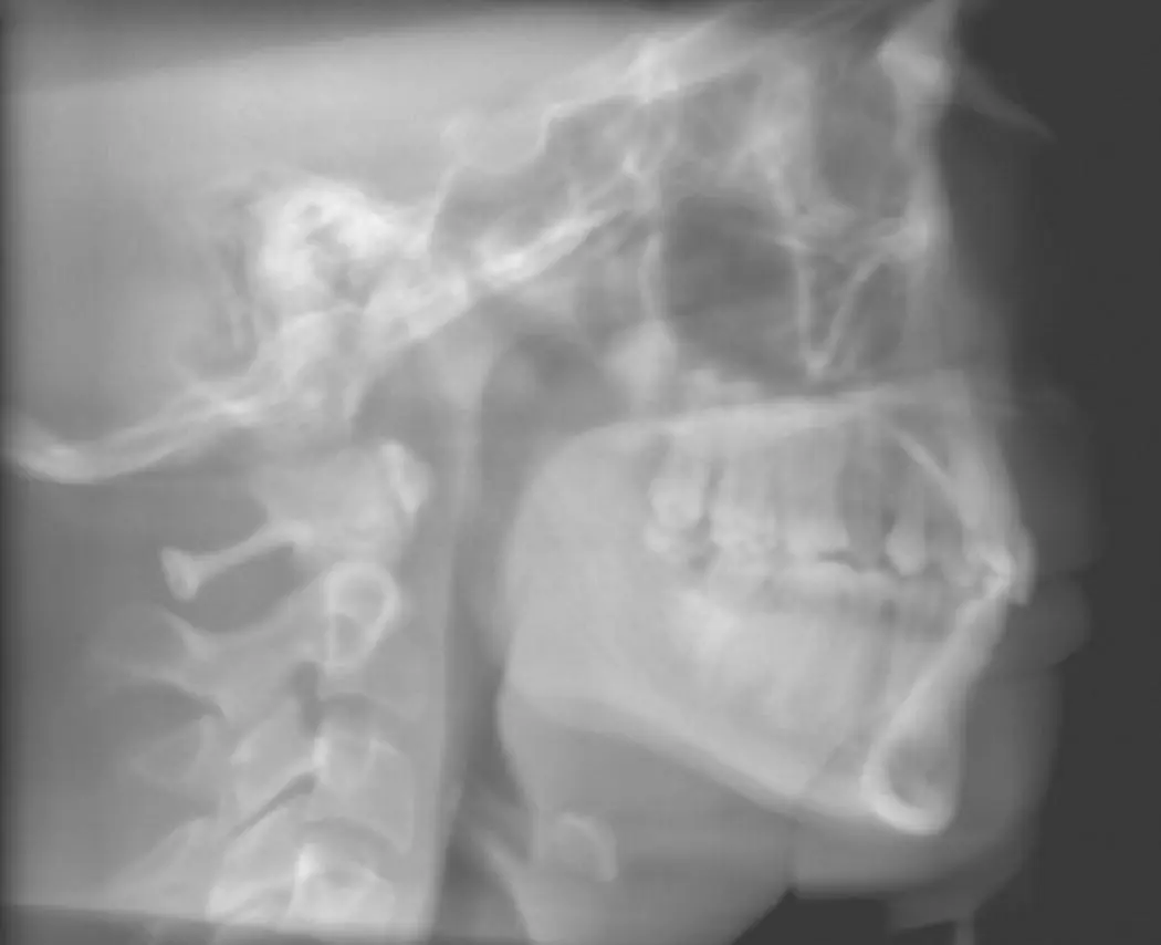
Figure 1.9. Reconstructed lateral cephalometric skull.
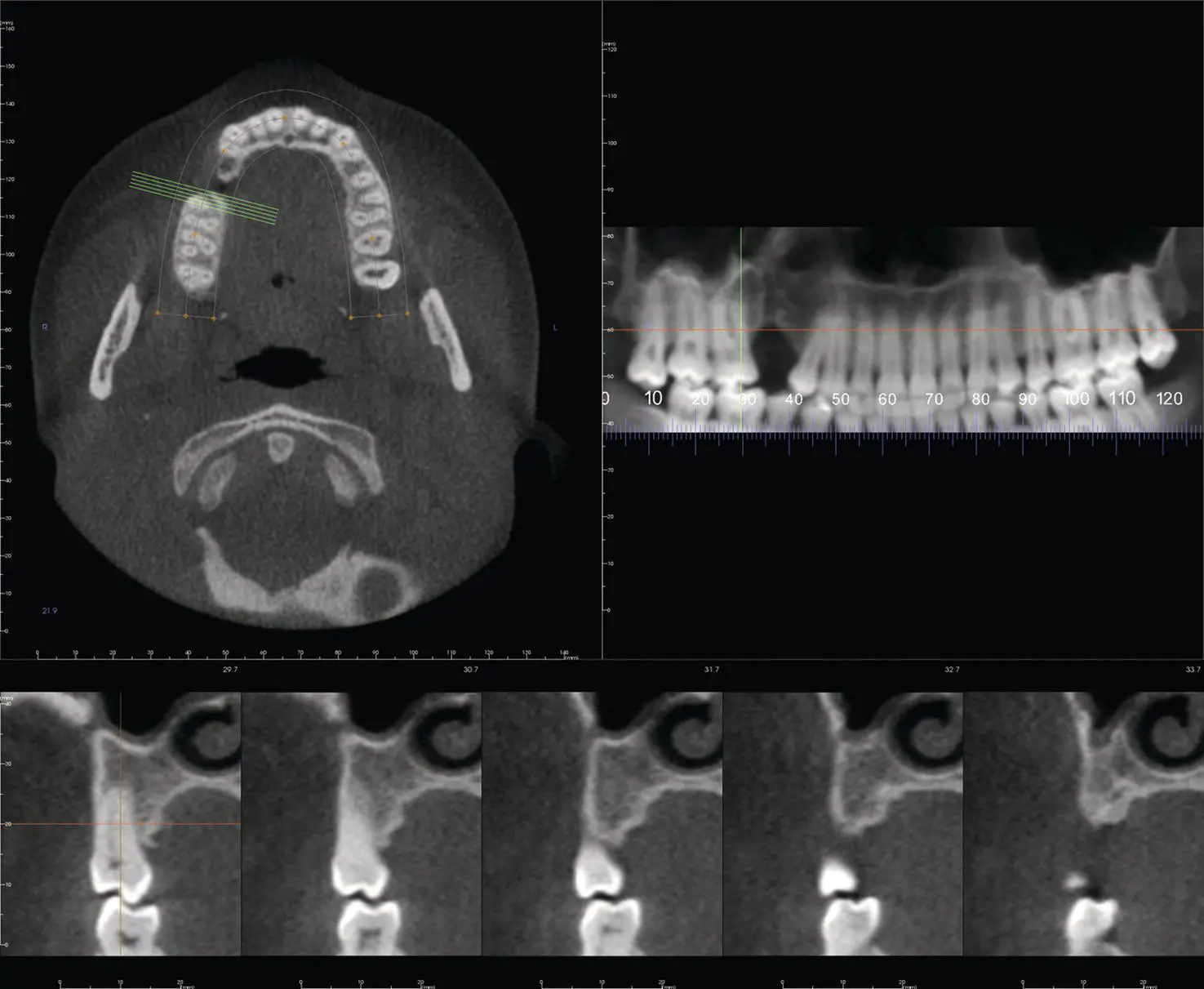
Figure 1.10. Cross‐sectional slices with axial view and reconstructed pantomograph.
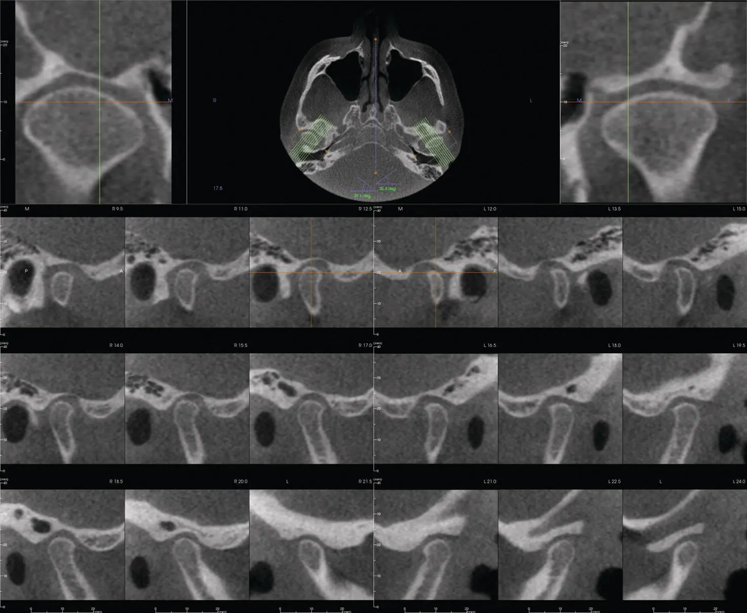
Figure 1.11. Temporomandibular joint view with rotated sagittal cross‐sectional slices.
3D Rendering
The most common form of 3D rendering offered in CBCT software is indirect volume rendering, which determines the grays of the voxels to create a 3D image ( Figure 1.12). Another form of 3D rendering is referred to as direct volume rendering, where the highest attenuation value for each voxel is used creating a maximum intensity projection (MIP) ( Figure 1.13).
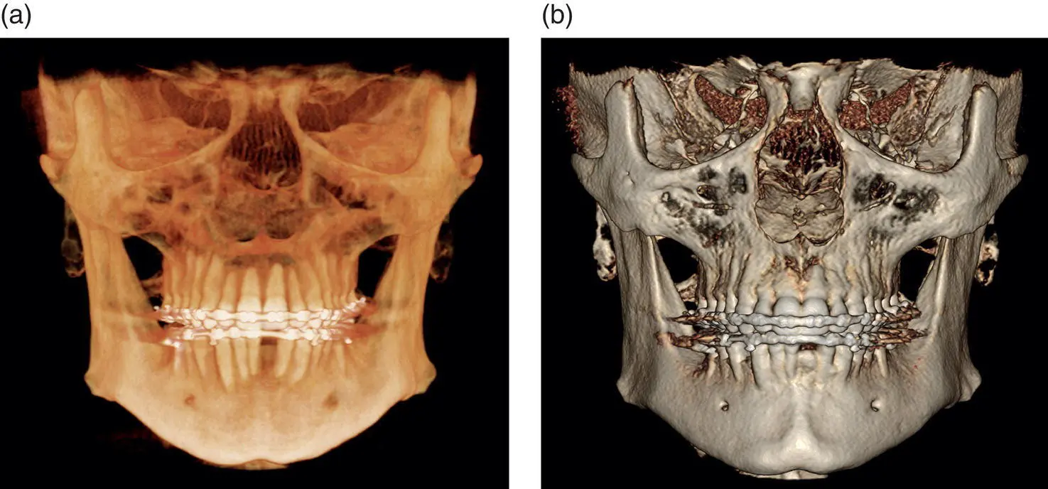
Figure 1.12. (a) 3D rendered view with teeth setting. (b) 3D rendered view with bone setting.
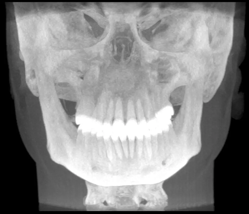
Figure 1.13. Maximum Intensity Projection (MIP) view.
Artifacts
Streak Artifacts/Undersampling
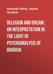
Streak artifacts occur when an object with high density (such as metallic restorations) creates areas of undersampling where no viable information is recorded. These present as white streaks ( Figure 1.14) radiating from the high‐density object. Beam hardening artifact is caused when low energy x‐rays are absorbed by high‐density objects creating an increase in x‐ray beam energy, which “hardens” the beam. This results as increased density (black) lines radiating from the high‐density object ( Figure 1.14). Care should be taken not to interpret anything in the streak artifacts and beam hardening. Aliasing is another form of undersampling, when too few images are acquired and appear as small lines throughout a scan ( Figure 1.15).
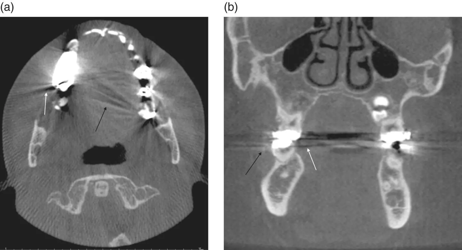
Figure 1.14. (a) Axial view showing streak artifact (black arrow) and beam hardening (white arrow) due to metallic restorations. (b) Coronal view showing streak artifact (black arrow) and beam hardening (white arrow) due to metallic restorations.
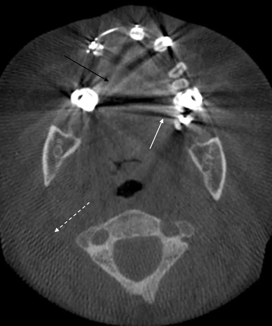
Figure 1.15. Axial view with metallic streak artifact (black arrow), beam hardening (white arrow), and aliasing of scan as linear radiolucent lines (white dotted arrow) throughout the entire image.
Motion Artifacts
Motion artifacts occur due to either normal pathophysiological movement or when the patient moves during a scan. This presents as double bony borders to ill‐defined bony borders ( Figures 1.16and 1.17). This can be minimized by restraining the patient’s head and using as short a scan time as possible.
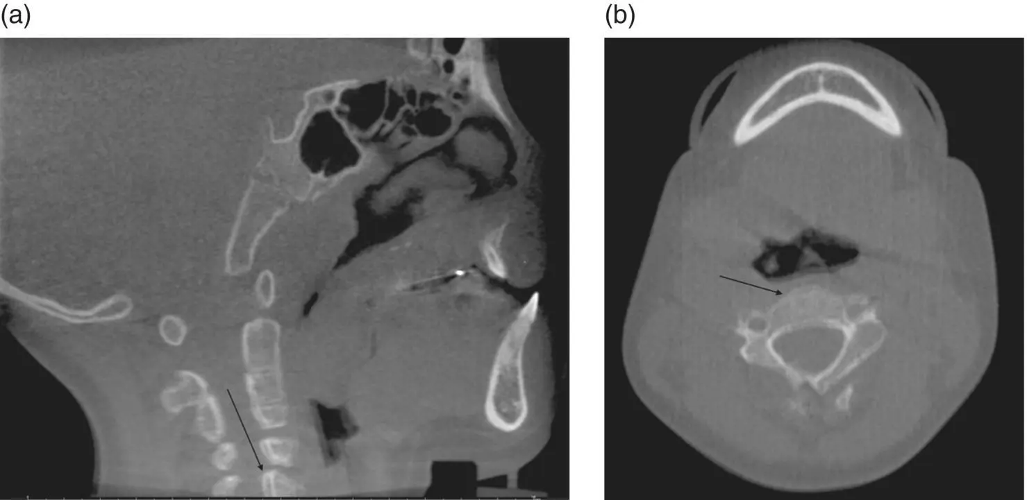
Figure 1.16. (a) Sagittal view showing motion artifact of the cervical vertebrae (black arrow). (b) Axial view showing motion artifact of the cervical vertebrae (black arrow).
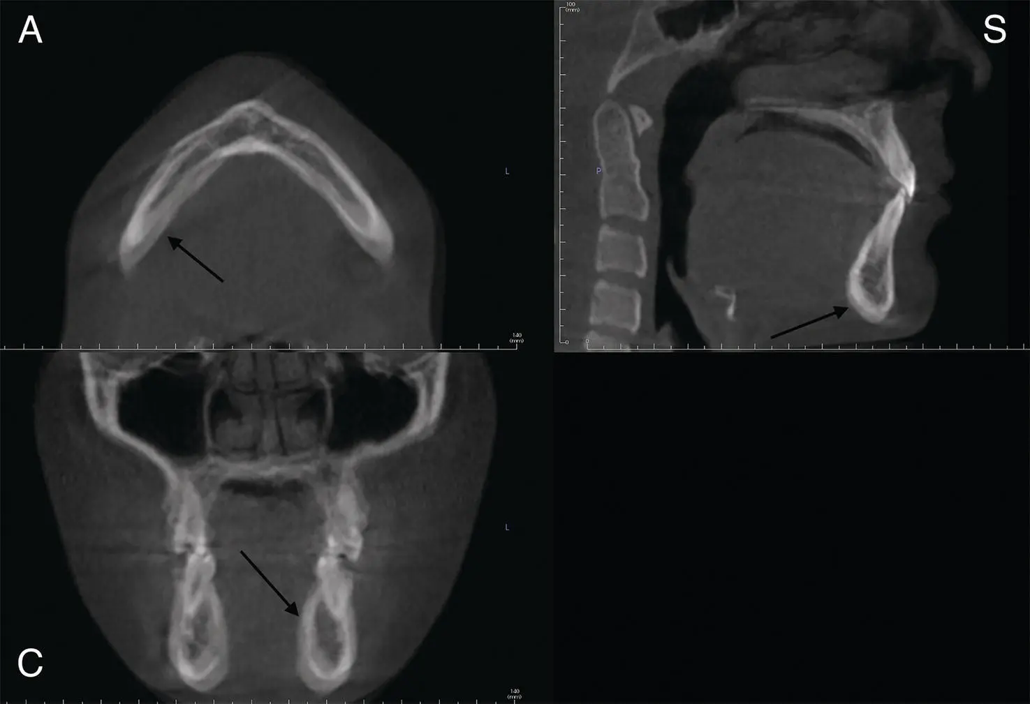
Figure 1.17. Axial (A), coronal (C), and sagittal (S) views with motion artifact (black arrows) throughout the jaws.
Ring Artifacts
Ring artifacts present as white or black circular artifacts. They typically indicate poor calibrations and imperfections in the scanner detection ( Figure 1.18).
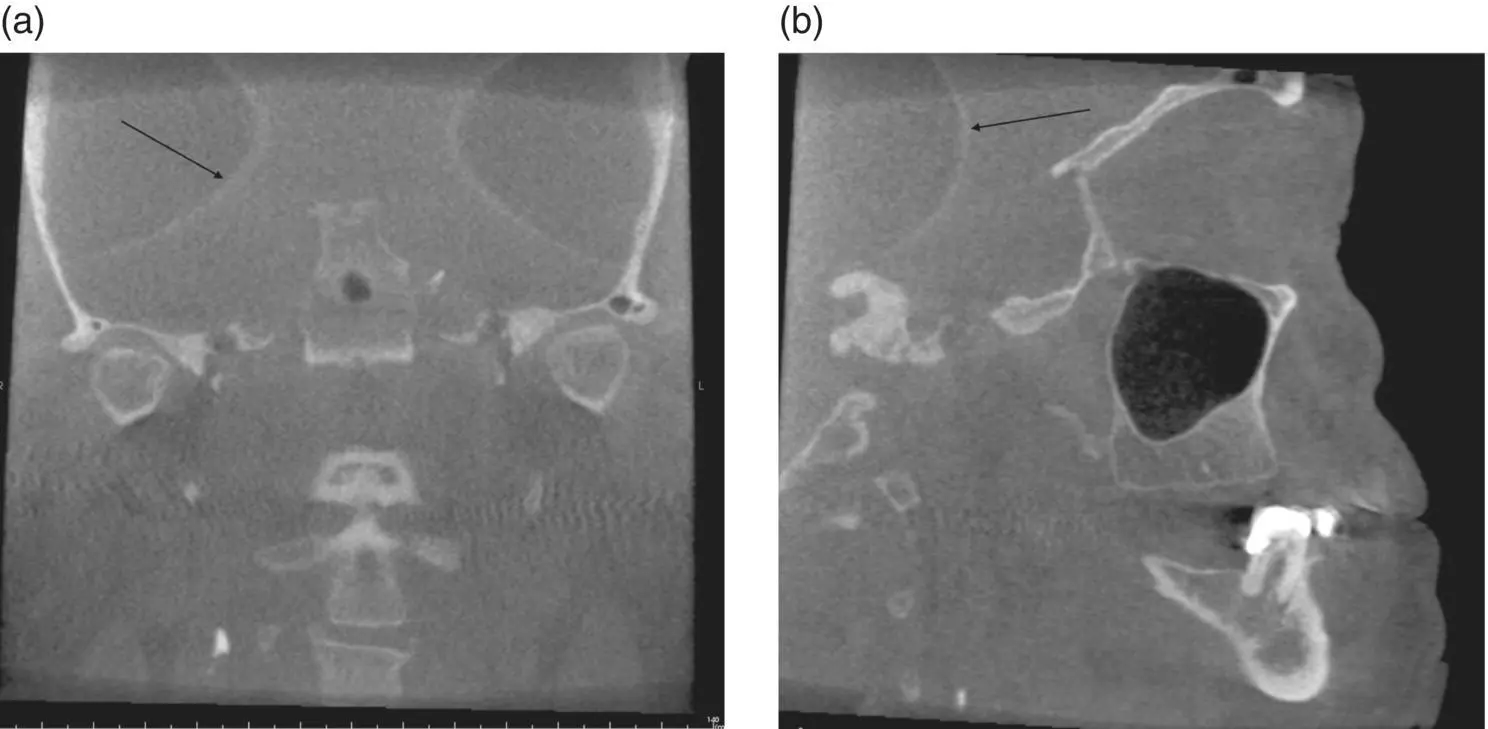
Figure 1.18. (a) Coronal view showing white ring artifacts (black arrow). (b) Sagittal view showing white ring artifacts (black arrow).
References
Conventional Computed Tomography and Cone Beam Computed Tomography
1 Dalrymple, N. C., Prasad, S. R., El‐Merhi, F. M., et al. (2007). Price of isotropy in multidetector CT. RadioGraphics, 27, 49–62.
2 Hounsfield, G. (1973). Computerized transverse axial scanning (tomography). 1. Description of the system. Br J Radiol, 46, 1016–22.
3 Mallaya, S., and Lam, E. (Ed.). (2019). White and Pharaoh’s Oral Radiology: Principles and Interpretation. Mosby.
4 Miles, D. E. (2008). Color Atlas of Cone Beam Volumetric Imaging for Dental Applications. Quintessence.
5 Popat, H., Drage, N., Durning, P. (2008). Mid‐line clefts of the cervical vertebrae—an incidental finding arising from cone beam computed tomography of the dental patient. Br Dental J, 204, 303–6.
Viewing CBCT Data
1 Cody, D. D. (2002). AAPM/RSNA physics tutorial for residents: topics in CT. Image processing in CT. Radiographics, 22, 1255–68.
2 Mallaya, S., and Lam, E. (Ed.). (2019). White and Pharaoh’s Oral Radiology: Principles and Interpretation. Mosby.
Artifacts
1 Mallaya, S., and Lam, E. (Ed.). (2019). White and Pharaoh’s Oral Radiology: Principles and Interpretation. Mosby.
2 Pauwels, R., Araki, K., Siewerdsen, J. H., et. al. (2015). Technical aspects of dental CBCT: state of the art. Dentomaxillofac Radiol, 44, 20140224.
3 Popilock, R., Sandrasagaren, K., Harris, L., et al. (2008). CT artifact recognition for the nuclear technologist. J Nucl Med Technol, 36, 79–81.
4 Zoller, J. E., and Nuegebauer, J. (2008). Cone‐Beam Volumetric Imaging in Dental, Oral, and Maxillofacial Medicine. Quintessence, Germany.
2 Cone Beam Computed Tomography Recommendations
Shawneen M. Gonzalez
Introduction
This chapter covers cone beam computed tomography recommendations and guidelines regarding use and imaging. The areas covered include recommendations from American endodontics, orthodontics, and periodontics specialty organizations along with sample cases.
Endodontics
The American Association of Endodontics (AAE) and the American Academy of Oral and Maxillofacial Radiology (AAOMR) have come out with two position papers regarding cone beam computed tomography (CBCT) use in endodontics.
Читать дальшеИнтервал:
Закладка:
Похожие книги на «Interpretation Basics of Cone Beam Computed Tomography»
Представляем Вашему вниманию похожие книги на «Interpretation Basics of Cone Beam Computed Tomography» списком для выбора. Мы отобрали схожую по названию и смыслу литературу в надежде предоставить читателям больше вариантов отыскать новые, интересные, ещё непрочитанные произведения.


Обсуждение, отзывы о книге «Interpretation Basics of Cone Beam Computed Tomography» и просто собственные мнения читателей. Оставьте ваши комментарии, напишите, что Вы думаете о произведении, его смысле или главных героях. Укажите что конкретно понравилось, а что нет, и почему Вы так считаете.