Ian Smith - Smith's Elements of Soil Mechanics
Здесь есть возможность читать онлайн «Ian Smith - Smith's Elements of Soil Mechanics» — ознакомительный отрывок электронной книги совершенно бесплатно, а после прочтения отрывка купить полную версию. В некоторых случаях можно слушать аудио, скачать через торрент в формате fb2 и присутствует краткое содержание. Жанр: unrecognised, на английском языке. Описание произведения, (предисловие) а так же отзывы посетителей доступны на портале библиотеки ЛибКат.

- Название:Smith's Elements of Soil Mechanics
- Автор:
- Жанр:
- Год:неизвестен
- ISBN:нет данных
- Рейтинг книги:5 / 5. Голосов: 1
-
Избранное:Добавить в избранное
- Отзывы:
-
Ваша оценка:
Smith's Elements of Soil Mechanics: краткое содержание, описание и аннотация
Предлагаем к чтению аннотацию, описание, краткое содержание или предисловие (зависит от того, что написал сам автор книги «Smith's Elements of Soil Mechanics»). Если вы не нашли необходимую информацию о книге — напишите в комментариях, мы постараемся отыскать её.
Smith's Elements of Soil Mechanics — читать онлайн ознакомительный отрывок
Ниже представлен текст книги, разбитый по страницам. Система сохранения места последней прочитанной страницы, позволяет с удобством читать онлайн бесплатно книгу «Smith's Elements of Soil Mechanics», без необходимости каждый раз заново искать на чём Вы остановились. Поставьте закладку, и сможете в любой момент перейти на страницу, на которой закончили чтение.
Интервал:
Закладка:
2.6 Determination of permeability in the field
2.6.1 Field pumping test
Laboratory tests can only determine k for the small sample of soil tested. To establish the permeability of a whole aquifer, a field pumping test is carried out. The test can be used to measure the average k value of a stratum of soil below the water table and is effective up to depths of about 45 m. Details of pumping test procedures are given in BS EN ISO 22282‐4:2012 (BSI, 2012) and BS ISO 14686:2003 (BSI, 2003).
A casing of about 400 mm diameter is driven to bedrock or to impervious stratum. Observation wells of at least 35 mm diameter are put down on radial lines from the casing, and both the casing and the observation wells are perforated to allow easy entrance of water. The test consists of pumping water out from the central casing at a measured rate, q and observing the resulting drawdown in groundwater level by means of the observation wells.
At least four observation wells, arranged in two rows at right angles to each other should be used although it may be necessary to install extra wells if the initial ones give irregular results. If there is a risk of fine soil particles clogging the observation wells then the wells should be surrounded by a suitably graded filter material (the design of filters is discussed later in this chapter) or a geofabric filter.
It may be that the site boundary conditions, e.g. a river, canal or a steep sloping surface of impermeable subsurface rock, a fault or a dyke, do not allow the two rows of observation wells to be placed at right angles. In such circumstances, the two rows of wells should be placed parallel to each other and at right angles to the offending boundary.
The minimum distance between the observation wells and the pumping well should be 10 times the radius of the pumping well and at least one of the observation wells in each row should be at a radial distance greater than twice the thickness of the ground being tested.
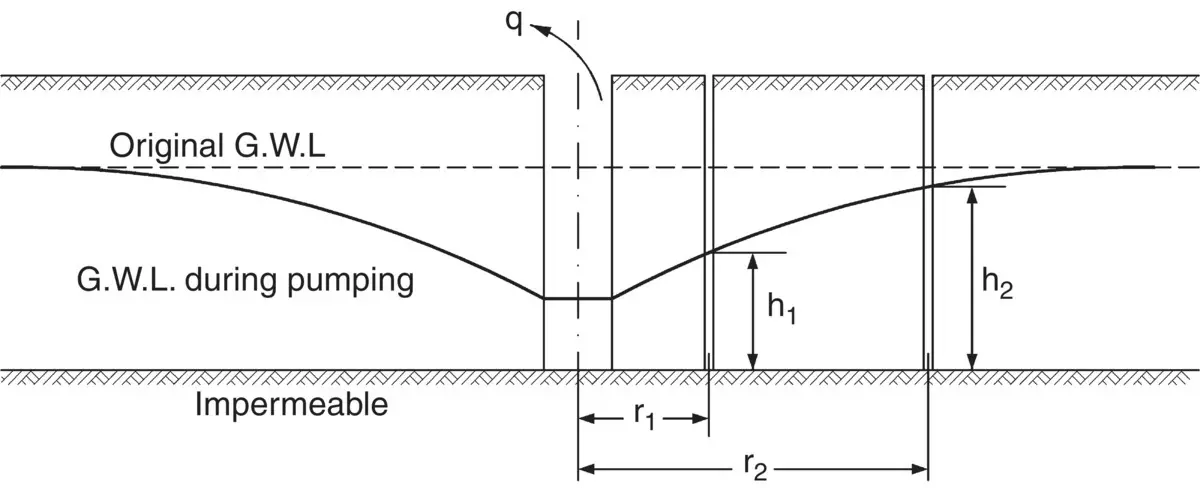
Fig. 2.6 Field pumping test.
In addition to the observation wells, an additional standpipe inside the pumping well is desirable so that a reliable record of the drawdown of the well itself can be obtained. Figure 2.6illustrates conditions during pumping.
Consider an intermediate distance r from the centre of the pumping well and let the height of the GWL above the impermeable layer during pumping be h.

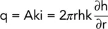
and 2πrh = area of the walls of an imaginary cylinder of radius r and height h.
Now,
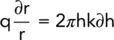
i.e.
and, integrating between test limits:
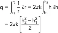
i.e.
(2.8) 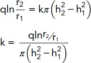
Pumping tests can be expensive as they require the installation of both the pumping and the observation wells as well as suitable pumping and support equipment. Care must be taken in the design of a suitable test programme and, before attempting to carry out any pumping test, reliable data should be obtained about the subsoil profile – by means of boreholes specially sunk for the purpose, if necessary. Suction pumps can be used where the groundwater does not have to be lowered by more than about 5 m below the intake chamber of the pump but for greater depths submersible pumps are generally necessary.
Example 2.3 Pumping test
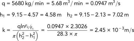
A 9.15 m thick layer of sandy soil overlies an impermeable rock. Groundwater level is at a depth of 1.22 m below the top of the soil. Water was pumped out of the soil from a central well at the rate of 5680 kg/min and the drawdown of the water table was noted in two observation wells. These two wells were on a radial line from the centre of the main well at distances of 3.05 and 30.5 m.
During pumping, the water level in the well nearest to the pump was 4.57 m below ground level and in the furthest well was 2.13 m below ground level.
Determine an average value for the permeability of the soil in m/s.
Solution:
2.6.2 Borehole tests
Where bedrock level is very deep or where the permeabilities of different strata are required, borehole permeability tests can be used. (See Chapter 7for details on borehole construction.)
In borehole permeability testing, open or closed systems can be used and procedures for all borehole hydraulic testing are given in BS EN ISO 22282:2012 (BSI, 2012).
Open system
A casing, perforated for a metre or so at its end, is driven into the ground. At intervals during the driving, the rate of flow of water placed under either a constant or a falling head within the borehole is determined. From this rate, together with knowledge of the hydraulic gradient and the cross‐sectional area through which the water flows from the borehole into the adjacent soil, a measure of the soil's permeability can be determined.
Closed system
Whereas an open system simply uses a hydraulic head of water in the borehole to cause water to flow into the soil at the perforated section, a closed system uses a pump to introduce water into the soil or rock under pressure and involves the use of one or more packers .
Packer test
This test is performed in a partly unlined borehole and can apply to both open and closed systems. The unlined section is the part that is placed under test and, since loose sands and gravels would collapse in on themselves, the test is predominantly used for measuring the permeability of a section of fissured rock mass. An inflatable rubber membrane known as a packer , wrapped around a vertical, perforated hydraulic pipe, is lowered to the depth in the borehole at which the rock is to be tested. The pipe extends below the base of the packer. The packer is inflated to form a watertight seal above the point to be tested. Water is then pumped through the pipe at a controlled pressure and the volume of water injected into the rock over a period of time is measured and used to establish the permeability of the rock.
A variation on this single packer test is to have a packer both above and beneath the section to be tested. Such an arrangement is known as a double packer test .
2.7 Approximation of coefficient of permeability
It is obvious that a soil's coefficient of permeability depends upon its porosity, which is itself related to the particle size distribution curve of the soil (a gravel is much more permeable than a clay). It would therefore seem possible to approximate the permeability of a soil given its particle size distribution, and typical ranges of k for different soil types are given below. In addition, k can be approximated for a clean sand thus:
Читать дальшеИнтервал:
Закладка:
Похожие книги на «Smith's Elements of Soil Mechanics»
Представляем Вашему вниманию похожие книги на «Smith's Elements of Soil Mechanics» списком для выбора. Мы отобрали схожую по названию и смыслу литературу в надежде предоставить читателям больше вариантов отыскать новые, интересные, ещё непрочитанные произведения.


Обсуждение, отзывы о книге «Smith's Elements of Soil Mechanics» и просто собственные мнения читателей. Оставьте ваши комментарии, напишите, что Вы думаете о произведении, его смысле или главных героях. Укажите что конкретно понравилось, а что нет, и почему Вы так считаете.