Ian Smith - Smith's Elements of Soil Mechanics
Здесь есть возможность читать онлайн «Ian Smith - Smith's Elements of Soil Mechanics» — ознакомительный отрывок электронной книги совершенно бесплатно, а после прочтения отрывка купить полную версию. В некоторых случаях можно слушать аудио, скачать через торрент в формате fb2 и присутствует краткое содержание. Жанр: unrecognised, на английском языке. Описание произведения, (предисловие) а так же отзывы посетителей доступны на портале библиотеки ЛибКат.

- Название:Smith's Elements of Soil Mechanics
- Автор:
- Жанр:
- Год:неизвестен
- ISBN:нет данных
- Рейтинг книги:5 / 5. Голосов: 1
-
Избранное:Добавить в избранное
- Отзывы:
-
Ваша оценка:
Smith's Elements of Soil Mechanics: краткое содержание, описание и аннотация
Предлагаем к чтению аннотацию, описание, краткое содержание или предисловие (зависит от того, что написал сам автор книги «Smith's Elements of Soil Mechanics»). Если вы не нашли необходимую информацию о книге — напишите в комментариях, мы постараемся отыскать её.
Smith's Elements of Soil Mechanics — читать онлайн ознакомительный отрывок
Ниже представлен текст книги, разбитый по страницам. Система сохранения места последней прочитанной страницы, позволяет с удобством читать онлайн бесплатно книгу «Smith's Elements of Soil Mechanics», без необходимости каждый раз заново искать на чём Вы остановились. Поставьте закладку, и сможете в любой момент перейти на страницу, на которой закончили чтение.
Интервал:
Закладка:
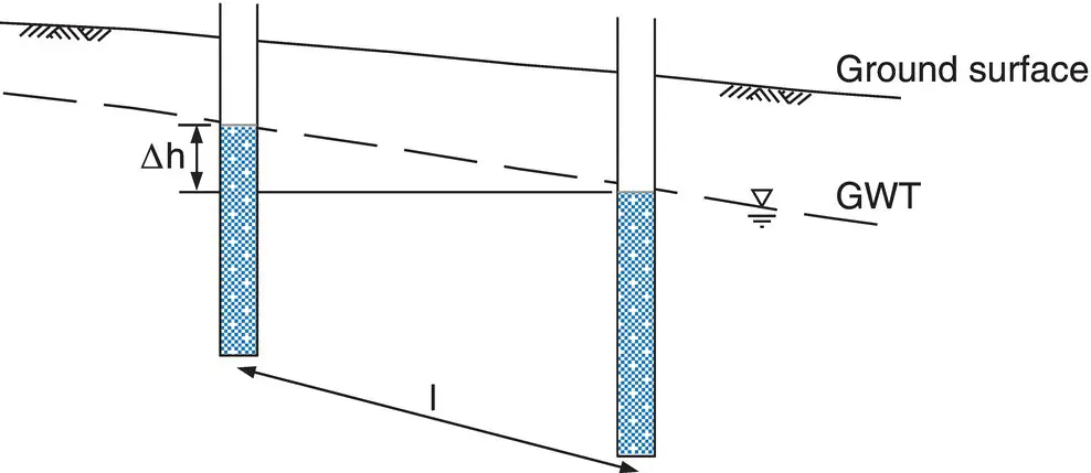
Fig. 2.3 Difference in hydraulic head between two points.
2.3 Darcy's law of saturated flow
In 1856, Darcy showed experimentally that a fluid's velocity of flow through a porous medium is directly related to the hydraulic gradient causing the flow, i.e.

where i = hydraulic gradient (the head loss per unit length), or

where C = a constant involving the properties of both the fluid and the porous material.
2.4 Coefficient of permeability, k
In soils, we are generally concerned with water flow, and the constant C is determined from tests in which the permeant is water. The particular value of the constant C obtained from these tests is known as the coefficient of permeability and is given the symbol k. The unit for k is m/s.
It is important to realise that when a soil is said to have a certain coefficient of permeability, this value only applies to water (at 20 °C). If heavy oil is used as the permeant, the value of C would be considerably less than k. Temperature causes variation in k, but in most soils work this is insignificant.
Provided that the hydraulic gradient is less than 1.0, as is the case in most seepage problems, the flow of water through a soil is linear and Darcy's law applies, i.e.
(2.5) 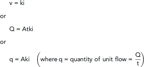
2.5 Determination of permeability in the laboratory
Laboratory tests can be performed to establish the coefficient of permeability for both granular and cohesive soils, and the testing procedures are described in BS EN ISO 17892‐11:2019. The tests involve placing the soil in a cylindrical permeameter , which can take different forms:
Rigid wall permeameter: standard cylindrical vessel (see Sections 2.5.1and 2.5.2) or oedometer ring within oedometer cell. (The oedometer test is described in Chapter 12.)
Flexible wall permeameter: rubber membrane placed around soil and tested in a triaxial cell, under required effective stress conditions. (The triaxial test is described in Chapter 4.)
In all cases, water is passed through the permeameter and the volume of water passing through the soil in a time interval, together with a measurable hydraulic gradient, can be used to establish the coefficient of permeability. Two of the most well‐established tests are the constant head test (for granular soils) and the falling head test (for cohesive soils).
2.5.1 Constant head test
The apparatus is shown in Fig. 2.4. Water flows through the soil under a head which is kept constant by means of the overflow arrangement. The head loss, h, between two points along the length of the sample, distance l apart, is measured by means of a manometer (in practice there are more than just two manometer tappings).
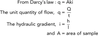
Hence, k can be found from the expression:
(2.6) 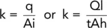
A series of readings can be obtained from each test and an average value of k determined. The test is suitable for gravels and sands, and could be used for many fill materials.
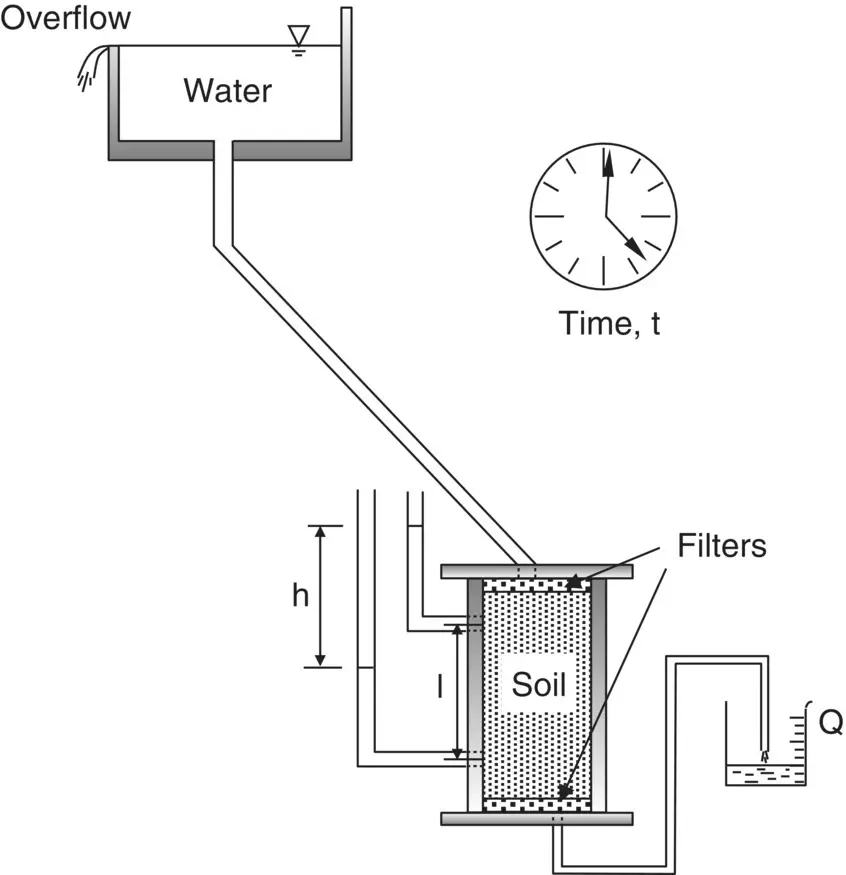
Fig. 2.4 The constant head permeameter.
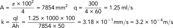
Example 2.1 Constant head test
In a constant head permeameter test, the following results were obtained:
Duration of test = 4.0 min
Quantity of water collected = 300 ml
Head difference in manometer = 50 mm
Distance between manometer tappings = 100 mm
Diameter of test sample = 100 mm
Determine the coefficient of permeability in m/s.
Solution:
2.5.2 The falling head permeameter
A sketch of the falling head permeameter is shown in Fig. 2.5. In this test, which is suitable for silts and some clays, the flow of water through the sample is measured at the inlet. The height, h 1, in the standpipe is measured and the valve is then opened as a stop clock is started. After a measured time, t, the height to which the water level has fallen, h 2, is determined.
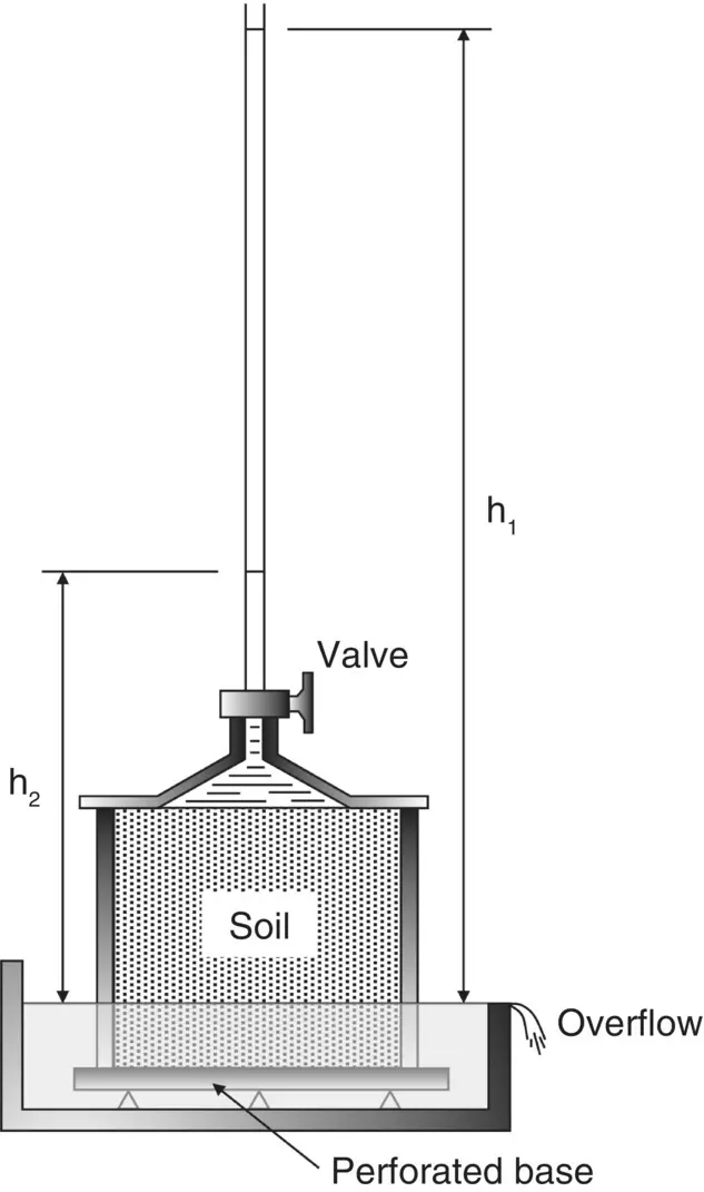
Fig. 2.5 The falling head permeameter.
k is given by the formula:
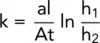
where
A = cross‐sectional area of sample
a = cross‐sectional area of standpipe
l = length of sample.
As just mentioned, during the test, the water in the standpipe falls from a height h 1to a final height h 2.
Let h be the height at some time, t.
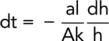
Consider a small time interval, dt, and let the change in the level of h during this time be −dh (negative as it is a drop in elevation).
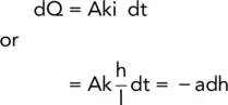
The quantity of flow through the sample in time dt = −adh and is given the symbol dQ. Now
Integrating between the test limits:
(2.7) 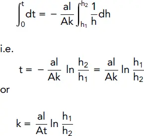
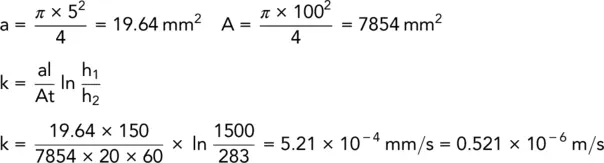
Example 2.2 Falling head permeameter
An undisturbed soil sample was tested in a falling head permeameter. The results were:
Initial head of water in standpipe = 1500 mm
Final head of water in standpipe = 283 mm
Duration of test = 20 minutes
Sample length = 150 mm
Sample diameter = 100 mm
Stand‐pipe diameter = 5 mm
Determine the permeability of the soil in m/s.
Solution:
2.5.3 The hydraulic consolidation cell (Rowe cell)
The Rowe cell (described in Chapter 12) was developed for carrying out consolidation tests. The apparatus can also be used for determining the permeability of a soil, though it is fairly rare to see this equipment in a commercial soils laboratory.
Читать дальшеИнтервал:
Закладка:
Похожие книги на «Smith's Elements of Soil Mechanics»
Представляем Вашему вниманию похожие книги на «Smith's Elements of Soil Mechanics» списком для выбора. Мы отобрали схожую по названию и смыслу литературу в надежде предоставить читателям больше вариантов отыскать новые, интересные, ещё непрочитанные произведения.


Обсуждение, отзывы о книге «Smith's Elements of Soil Mechanics» и просто собственные мнения читателей. Оставьте ваши комментарии, напишите, что Вы думаете о произведении, его смысле или главных героях. Укажите что конкретно понравилось, а что нет, и почему Вы так считаете.