Flow-Induced Vibration Handbook for Nuclear and Process Equipment
Здесь есть возможность читать онлайн «Flow-Induced Vibration Handbook for Nuclear and Process Equipment» — ознакомительный отрывок электронной книги совершенно бесплатно, а после прочтения отрывка купить полную версию. В некоторых случаях можно слушать аудио, скачать через торрент в формате fb2 и присутствует краткое содержание. Жанр: unrecognised, на английском языке. Описание произведения, (предисловие) а так же отзывы посетителей доступны на портале библиотеки ЛибКат.
- Название:Flow-Induced Vibration Handbook for Nuclear and Process Equipment
- Автор:
- Жанр:
- Год:неизвестен
- ISBN:нет данных
- Рейтинг книги:3 / 5. Голосов: 1
-
Избранное:Добавить в избранное
- Отзывы:
-
Ваша оценка:
Flow-Induced Vibration Handbook for Nuclear and Process Equipment: краткое содержание, описание и аннотация
Предлагаем к чтению аннотацию, описание, краткое содержание или предисловие (зависит от того, что написал сам автор книги «Flow-Induced Vibration Handbook for Nuclear and Process Equipment»). Если вы не нашли необходимую информацию о книге — напишите в комментариях, мы постараемся отыскать её.
Flow-Induced Vibration Handbook for Nuclear and Process Equipment Helps readers understand and apply techniques for preventing fatigue and fretting-wear damage due to flow-induced vibration at the design stage Covers components including nuclear reactor internals, nuclear fuels, piping systems, and various types of heat exchangers Features examples of vibration-related failures caused by fatigue or fretting-wear in nuclear and process equipment Includes a detailed overview of state-of-the-art flow-induced vibration technology with an emphasis on two-phase flow-induced vibration Covering all relevant aspects of flow-induced vibration technology,
is required reading for professional mechanical engineers and researchers working in the nuclear, petrochemical, aerospace, and process industries, as well as graduate students in mechanical engineering courses on flow-induced vibration.
Flow-Induced Vibration Handbook for Nuclear and Process Equipment — читать онлайн ознакомительный отрывок
Ниже представлен текст книги, разбитый по страницам. Система сохранения места последней прочитанной страницы, позволяет с удобством читать онлайн бесплатно книгу «Flow-Induced Vibration Handbook for Nuclear and Process Equipment», без необходимости каждый раз заново искать на чём Вы остановились. Поставьте закладку, и сможете в любой момент перейти на страницу, на которой закончили чтение.
Интервал:
Закладка:
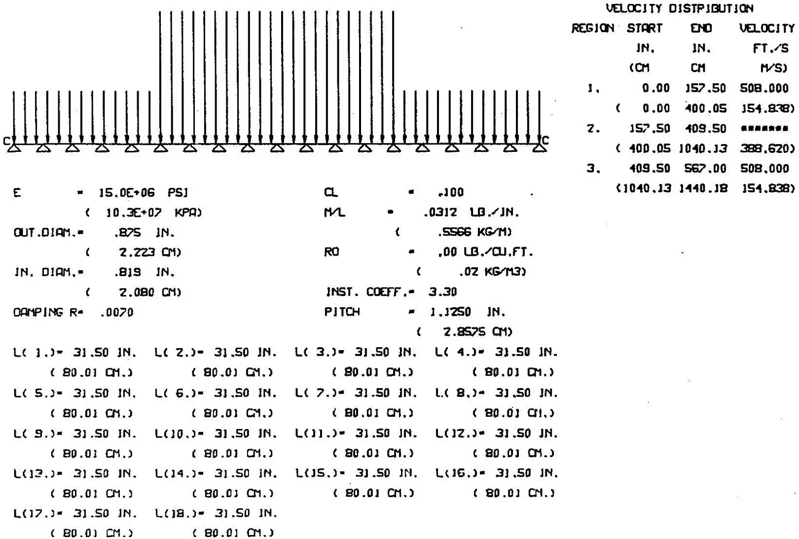
Fig. 2-4 Gap Cross‐Flow Distribution Along a Typical Condenser Tube.
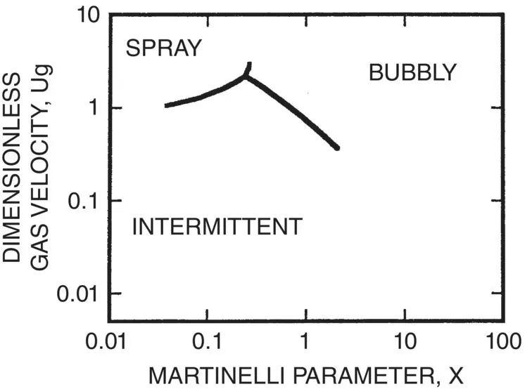
Fig. 2-5 Flow Pattern Map for Two‐Phase Flow Across Cylinder Arrays Using Flow Pattern Boundaries (Grant and Chisholm (1979) and Axes Parameters from McNaught (1982)).
2.2.4 Two‐Phase Flow Regime
Some knowledge of flow regime is necessary to assess flow‐induced vibration in two‐phase flow. Flow regimes are governed by a number of parameters, such as surface tension, density of each phase, viscosity of each phase, geometry of flow path, mass flux, void fraction and gravity forces. Flow regime conditions are usually presented in terms of dimensionless parameters in the form of a flow regime map. Grant (1975) and Grant and Chisholm (1979) used available data to develop the flow regime boundaries shown in Fig. 2-5. The axes on the Grant flow regime map are defined in terms of a Martinelli parameter, X , and a dimensionless gas velocity, U g. The Martinelli parameter is formulated as follows:
(2‐7) 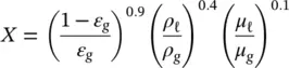
where μ ℓand μ gare the dynamic viscosity of the liquid and gas phases, respectively. The dimensionless gas velocity is defined as follows:
(2‐8) 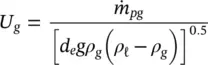
where  is the pitch mass flux of the gas phase, d e≅ 2( P − D ) is the equivalent hydraulic diameter and g is acceleration due to gravity.
The Grant map of Fig. 2-5shows three flow regimes: spray, bubbly and intermittent. The terms spray and bubbly are used loosely here. Perhaps they would be more appropriately defined as “continuous flow” covering the whole range from true bubbly flow to wall‐type flow to spray flow. Intermittent flow is characterized by periods of flooding (mostly liquid) followed by bursts of mostly gas flow. As discussed by Pettigrew et al (1989a) and Pettigrew and Taylor (1994), this is an undesirable flow regime from a vibration point‐of‐view. Thus, intermittent flow should be avoided in two‐phase heat exchange components and, particularly, in the U‐bend region of steam generators.
Flow regime is discussed in more detail in Chapter 3.
2.3 Dynamic Parameters
The relevant dynamic parameters for multi‐span heat exchanger tubes are mass and damping.
2.3.1 Hydrodynamic Mass
Hydrodynamic mass is the equivalent dynamic mass of external fluid vibrating with the tube. In liquid flow, the hydrodynamic mass per unit length of a tube confined within a tube bundle may be expressed by

Fig. 2-6 Hydrodynamic Mass in Two‐Phase Cross Flow: Comparison Between Theory and Experiments. (Note that m ℓis the hydrodynamic mass per unit length in liquid.)
(2.9) 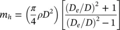
where D eis the equivalent diameter of the surrounding tubes and the ratio D e/ D is a measure of confinement. The effect of confinement is formulated by
(2‐10) 
for a tube inside a triangular tube bundle (Rogers et al, 1984). Similarly, for a square tube bundle (Pettigrew et al, 1989a) confinement may be approximated by
(2‐11) 
The hydrodynamic mass of tube bundles subjected to two‐phase cross flow may be calculated with Eq. (2-9)provided that the homogeneous density of the two‐phase mixture, ρ TP, is used in the formulation (Pettigrew et al, 1989a). Figure 2-6compares Eq. (2-9)to experimental data.
The total dynamic mass of the tube per unit length, m , comprises the hydrodynamic mass per unit length, m h, the tube mass per unit length, m t, and the mass per unit length of the fluid inside the tube, m i:
(2‐12) 
See Chapter 4for more detail on hydrodynamic mass.
2.3.2 Damping
Vibration energy dissipation (damping) is an important parameter in limiting vibration. Damping in single‐ and two‐phase flows is discussed in detail in Chapters 5and 6, respectively.
Heat Exchanger Tubes in Gases
As discussed in Pettigrew et al (1986), the dominant damping mechanism in heat exchangers with gas on the shell‐side is friction between tubes and tube supports. The available information on damping of heat exchanger tubes in gases has been reviewed. This work yielded the following design recommendation for estimating the friction damping ratio, ζ F, in percent:
(2‐13) 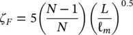
which takes into account the effect of support thickness, L , span length, ℓ m, and number of spans, N .
Heat Exchanger Tubes in Liquids
As discussed in Chapter 5, there are three important energy dissipation mechanisms that contribute to damping of multi‐span heat exchanger tubes with liquids on the shell‐side. These are viscous damping between tube and liquid, squeeze‐film damping in the clearance between tube and tube support, and friction damping at the support. Thus, the total tube damping, ζ T, which we define as the ratio of actual to critical damping in percent, is expressed by
(2‐14) 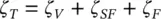
where, ζ V, ζ SFand ζ Fare, respectively, the viscous, squeeze‐film and friction damping ratios.
Tube‐to‐fluid viscous damping is related to the Stokes number, πfD 2/2 v , and the degree of confinement of the heat exchanger tube within the tube bundle or D / D e. Rogers et al (1984) developed a simplified formulation for viscous damping, valid for πfD 2/2 v > 3300 and D / D e< 0.5 which covers most heat exchangers. Their simplified expression for ζ V(in percent) is
Читать дальшеИнтервал:
Закладка:
Похожие книги на «Flow-Induced Vibration Handbook for Nuclear and Process Equipment»
Представляем Вашему вниманию похожие книги на «Flow-Induced Vibration Handbook for Nuclear and Process Equipment» списком для выбора. Мы отобрали схожую по названию и смыслу литературу в надежде предоставить читателям больше вариантов отыскать новые, интересные, ещё непрочитанные произведения.


Обсуждение, отзывы о книге «Flow-Induced Vibration Handbook for Nuclear and Process Equipment» и просто собственные мнения читателей. Оставьте ваши комментарии, напишите, что Вы думаете о произведении, его смысле или главных героях. Укажите что конкретно понравилось, а что нет, и почему Вы так считаете.