Flow-Induced Vibration Handbook for Nuclear and Process Equipment
Здесь есть возможность читать онлайн «Flow-Induced Vibration Handbook for Nuclear and Process Equipment» — ознакомительный отрывок электронной книги совершенно бесплатно, а после прочтения отрывка купить полную версию. В некоторых случаях можно слушать аудио, скачать через торрент в формате fb2 и присутствует краткое содержание. Жанр: unrecognised, на английском языке. Описание произведения, (предисловие) а так же отзывы посетителей доступны на портале библиотеки ЛибКат.
- Название:Flow-Induced Vibration Handbook for Nuclear and Process Equipment
- Автор:
- Жанр:
- Год:неизвестен
- ISBN:нет данных
- Рейтинг книги:3 / 5. Голосов: 1
-
Избранное:Добавить в избранное
- Отзывы:
-
Ваша оценка:
Flow-Induced Vibration Handbook for Nuclear and Process Equipment: краткое содержание, описание и аннотация
Предлагаем к чтению аннотацию, описание, краткое содержание или предисловие (зависит от того, что написал сам автор книги «Flow-Induced Vibration Handbook for Nuclear and Process Equipment»). Если вы не нашли необходимую информацию о книге — напишите в комментариях, мы постараемся отыскать её.
Flow-Induced Vibration Handbook for Nuclear and Process Equipment Helps readers understand and apply techniques for preventing fatigue and fretting-wear damage due to flow-induced vibration at the design stage Covers components including nuclear reactor internals, nuclear fuels, piping systems, and various types of heat exchangers Features examples of vibration-related failures caused by fatigue or fretting-wear in nuclear and process equipment Includes a detailed overview of state-of-the-art flow-induced vibration technology with an emphasis on two-phase flow-induced vibration Covering all relevant aspects of flow-induced vibration technology,
is required reading for professional mechanical engineers and researchers working in the nuclear, petrochemical, aerospace, and process industries, as well as graduate students in mechanical engineering courses on flow-induced vibration.
Flow-Induced Vibration Handbook for Nuclear and Process Equipment — читать онлайн ознакомительный отрывок
Ниже представлен текст книги, разбитый по страницам. Система сохранения места последней прочитанной страницы, позволяет с удобством читать онлайн бесплатно книгу «Flow-Induced Vibration Handbook for Nuclear and Process Equipment», без необходимости каждый раз заново искать на чём Вы остановились. Поставьте закладку, и сможете в любой момент перейти на страницу, на которой закончили чтение.
Интервал:
Закладка:
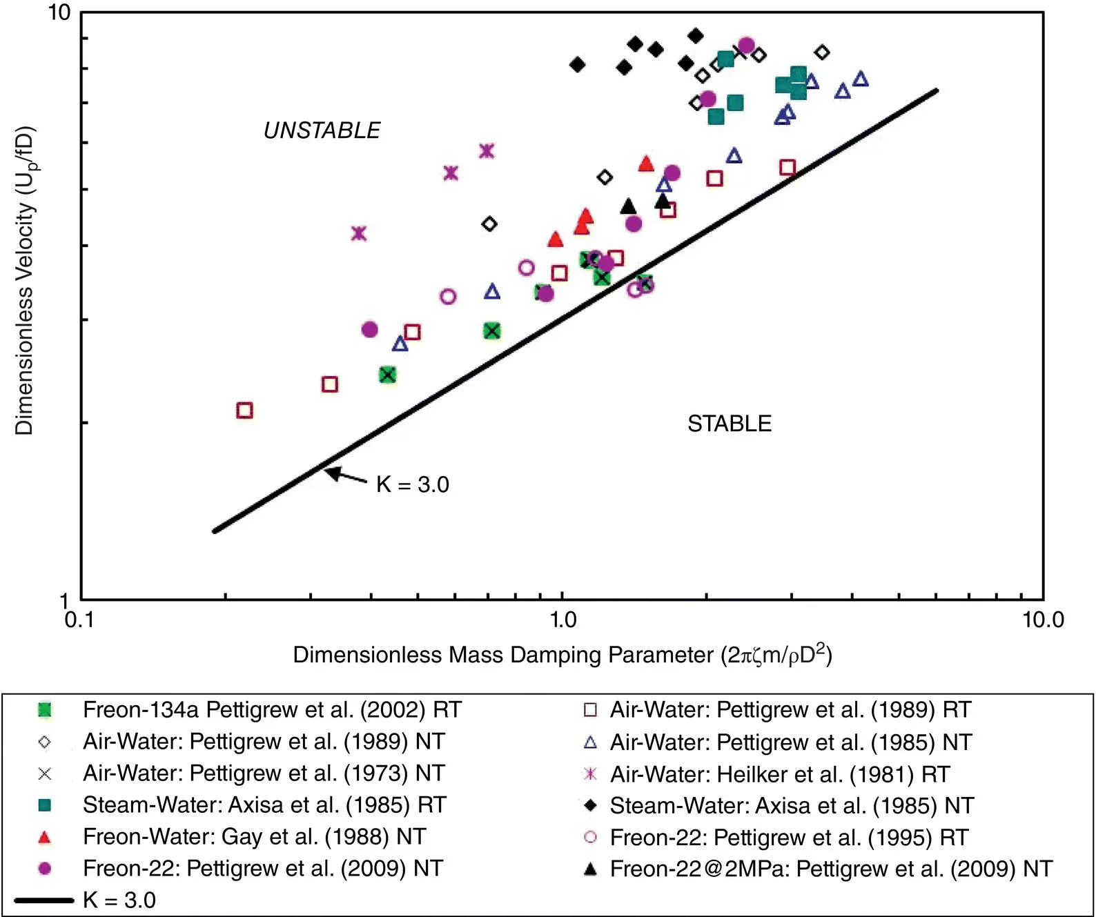
Fig. 2-12 Fluidelastic Instability Data in Two‐Phase Cross Flow.
Fluidelastic instability in two‐phase cross flow can also be formulated using Eq. (2-25). As shown in Fig. 2-12, a fluidelastic instability constant K = 3.0 is also recommended for two‐phase cross flow, but only for tube bundles of P / D > 1.47 which is the case for many steam generators. Lower values of K must be used for bundles of P/D ratios lower than 1.47, as discussed by Pettigrew and Taylor (1994). As shown in Fig. 2-13, the expression
(2‐26) 
would be a reasonable design guideline for P/D < 1.47.
2.4.2 Random Turbulence Excitation
Random turbulence excitation is a significant excitation mechanism in both liquid and two‐phase cross flow. Formulations for single‐ and two‐phase cross flow are given below. The topics are discussed in more detail in Chapters 9and 10for single‐ and two‐phase flow, respectively.
To be able to compare data and find an upper bound, the excitation forces must be presented as a normalized excitation force spectra. Researchers in this field such as Taylor and Pettigrew (1998), and Pettigrew and Gorman (1981) have used various methods of normalizing their results. Therefore, it was necessary to select one means of normalization and apply it to all of the data. The adopted method is the “equivalent power spectral density (EPSD),” first described by Axisa et al (1990).
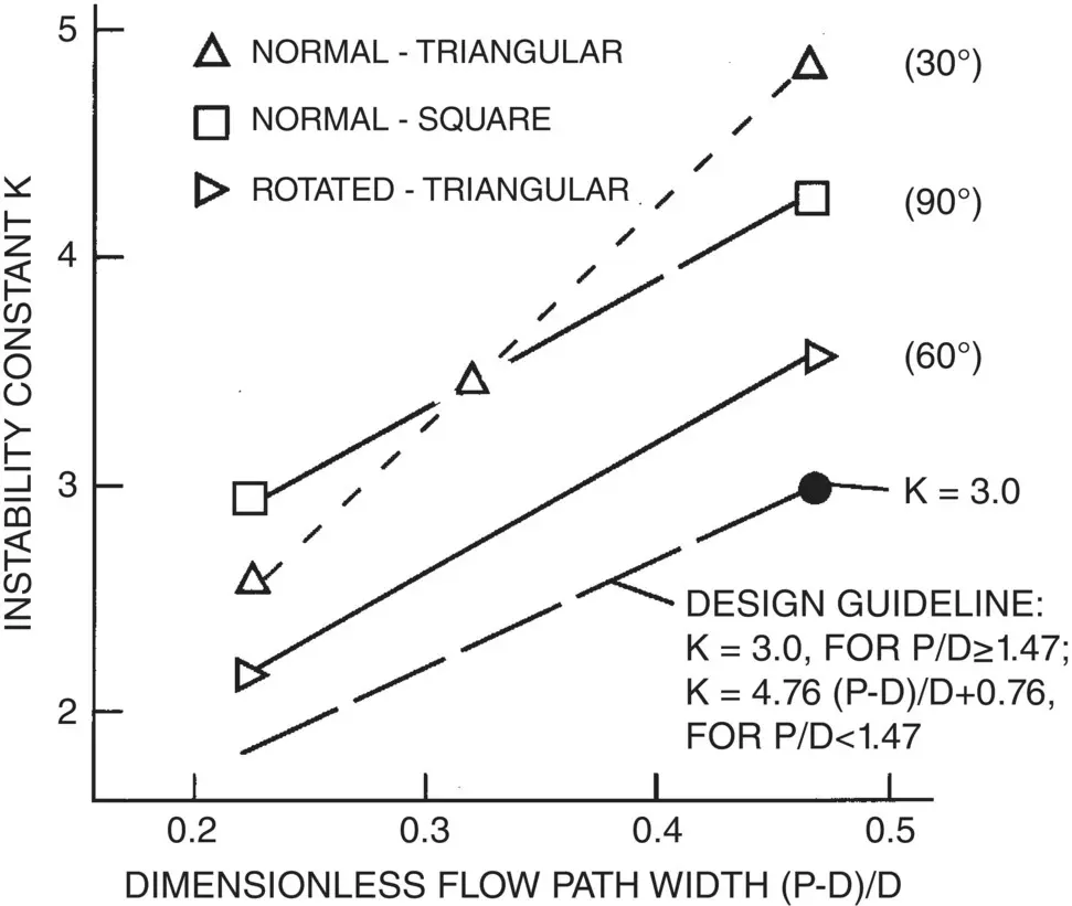
Fig. 2-13 Effect of P/D on Fluidelastic Instability Constant in Two‐Phase Cross Flow.
The power spectral density (PSD),  , can be rendered dimensionless using a pressure scaling factor, p o, and a frequency scaling factor, f o, as follows:
(2‐27) 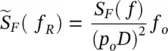
where, f Ris the reduced frequency, defined as f / f o, and D is the tube diameter.
A difficulty arises in the calculation of S F( f ) because the correlation length, λ c, is rarely known. Axisa et al (1990) present a dimensionless EPSD,  , defined as follows:
(2‐28) 
where, L eis the excited tube length. Using this definition, the dimensionless EPSD for Mode 1 can be defined in terms of the mean square of tube displacement,  as follows:
(2‐29) 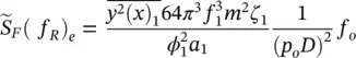
where, ϕ 1( x 1) is the normalized mode shape for the 1 stmode, a 1is the numerical coefficient for the 1 stmode, f 1is the 1 stmode tube natural frequency, m is the total tube mass (tube mass + hydrodynamic mass) and ζ 1is the damping ratio for the 1 stmode. Values of  and a 1are 2.0 and 1.1, respectively, for pinned‐pinned end conditions.
Using Eq. (2-29), the mean square of tube displacement can be found without knowledge of the correlation length. Instead, a small correlation length is assumed. To correctly compare spectra obtained using experimental rigs with varying geometries, it is necessary to define a dimensionless reference EPSD,  , based on a reference excited tube length, L o, and a reference tube diameter, D o, as follows:
(2‐30) 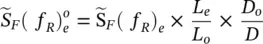
where, L e, is the excited tube length. In this chapter, reference lengths of L o= 1 m and D o= 0.02 m are applied.
Single‐Phase Cross Flow
In single‐phase cross flow, two distinct flow fields are possible. Interior tubes, well within a heat exchanger tube bundle, are excited by turbulence generated within the bundle. This excitation is governed by the tube bundle geometry. On the other hand, upstream or inlet tubes are excited by turbulence generated by upstream components such as inlet nozzles, entrance ports and upstream piping elements. Upstream turbulence levels are governed by the upstream flow path geometry and are very often much larger than those generated within the bundle. Such excitation is often referred to as far‐field excitation.
Random turbulence excitation is usually not a problem with gas or vapor cross flow. The pressure fluctuations and resulting excitation forces due to gas cross flow at a given velocity are generally an order of magnitude less than those for a liquid or two‐phase mixture at the same velocity. However, gas velocities can be extremely high and at high pressure the densities can be significant. Therefore, some consideration should be given to random excitation in high‐pressure gas heat exchangers.
Taylor and Pettigrew (2000) combined data from many sources to arrive at the reference EPSD guideline shown in Fig. 2-14. The lower bound, shown in Fig. 2-14, should be used when the upstream turbulence is less than or equal to the turbulence within the tube bundle. The upper bound, shown in Fig. 2-14, should be used if the upstream turbulence exceeds the turbulence inside the tube bundle. The boundaries are defined as follows:
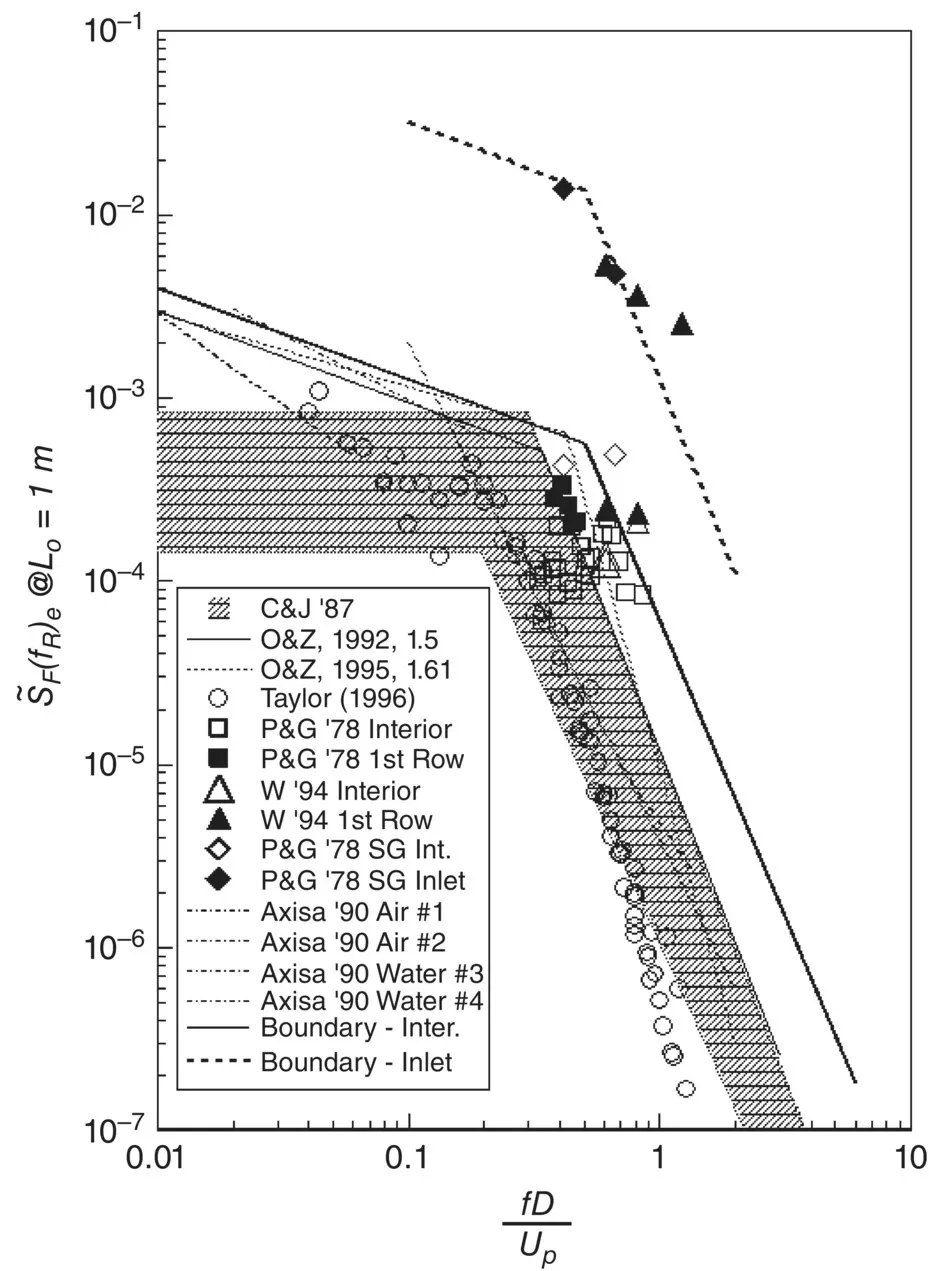
Fig. 2-14 Proposed Guideline for Single‐Phase Random Excitation Forces (References Provided in the Legend can be found in Taylor and Pettigrew (2000)).
(2.31) 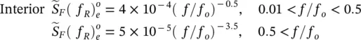
(2‐32) 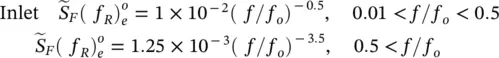
Интервал:
Закладка:
Похожие книги на «Flow-Induced Vibration Handbook for Nuclear and Process Equipment»
Представляем Вашему вниманию похожие книги на «Flow-Induced Vibration Handbook for Nuclear and Process Equipment» списком для выбора. Мы отобрали схожую по названию и смыслу литературу в надежде предоставить читателям больше вариантов отыскать новые, интересные, ещё непрочитанные произведения.


Обсуждение, отзывы о книге «Flow-Induced Vibration Handbook for Nuclear and Process Equipment» и просто собственные мнения читателей. Оставьте ваши комментарии, напишите, что Вы думаете о произведении, его смысле или главных героях. Укажите что конкретно понравилось, а что нет, и почему Вы так считаете.