Flow-Induced Vibration Handbook for Nuclear and Process Equipment
Здесь есть возможность читать онлайн «Flow-Induced Vibration Handbook for Nuclear and Process Equipment» — ознакомительный отрывок электронной книги совершенно бесплатно, а после прочтения отрывка купить полную версию. В некоторых случаях можно слушать аудио, скачать через торрент в формате fb2 и присутствует краткое содержание. Жанр: unrecognised, на английском языке. Описание произведения, (предисловие) а так же отзывы посетителей доступны на портале библиотеки ЛибКат.
- Название:Flow-Induced Vibration Handbook for Nuclear and Process Equipment
- Автор:
- Жанр:
- Год:неизвестен
- ISBN:нет данных
- Рейтинг книги:3 / 5. Голосов: 1
-
Избранное:Добавить в избранное
- Отзывы:
-
Ваша оценка:
Flow-Induced Vibration Handbook for Nuclear and Process Equipment: краткое содержание, описание и аннотация
Предлагаем к чтению аннотацию, описание, краткое содержание или предисловие (зависит от того, что написал сам автор книги «Flow-Induced Vibration Handbook for Nuclear and Process Equipment»). Если вы не нашли необходимую информацию о книге — напишите в комментариях, мы постараемся отыскать её.
Flow-Induced Vibration Handbook for Nuclear and Process Equipment Helps readers understand and apply techniques for preventing fatigue and fretting-wear damage due to flow-induced vibration at the design stage Covers components including nuclear reactor internals, nuclear fuels, piping systems, and various types of heat exchangers Features examples of vibration-related failures caused by fatigue or fretting-wear in nuclear and process equipment Includes a detailed overview of state-of-the-art flow-induced vibration technology with an emphasis on two-phase flow-induced vibration Covering all relevant aspects of flow-induced vibration technology,
is required reading for professional mechanical engineers and researchers working in the nuclear, petrochemical, aerospace, and process industries, as well as graduate students in mechanical engineering courses on flow-induced vibration.
Flow-Induced Vibration Handbook for Nuclear and Process Equipment — читать онлайн ознакомительный отрывок
Ниже представлен текст книги, разбитый по страницам. Система сохранения места последней прочитанной страницы, позволяет с удобством читать онлайн бесплатно книгу «Flow-Induced Vibration Handbook for Nuclear and Process Equipment», без необходимости каждый раз заново искать на чём Вы остановились. Поставьте закладку, и сможете в любой момент перейти на страницу, на которой закончили чтение.
Интервал:
Закладка:
Ziada et al (1989) propose a resonance parameter to assess susceptibility to resonance. For staggered arrays (triangular), this parameter has the form
(2‐43a) 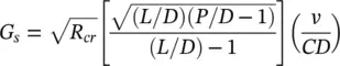
where R cris the Reynolds number based on the critical flow velocity at resonance, and v is the kinematic viscosity for the shell-side gas. The resonance parameter, G s, is correlated versus the flow path parameter, L/h , in Fig. 2-19b for both resonance and non‐resonance data. The parameter L/h is defined in Ziada et al (1989).
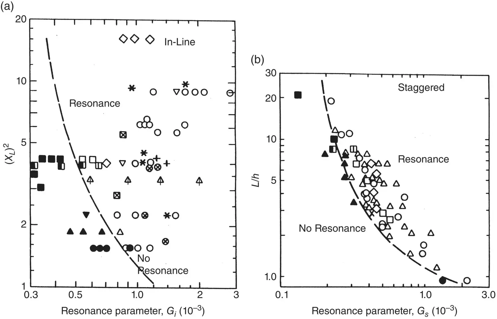
Fig. 2-19 Proposed Damping Criteria (Resonance Parameter) for: a) In‐Line (Square) Arrays; b) Staggered (Triangular) Arrays (Ziada et al, 1989 / with permission of Elsevier).
Similarly, for in‐line arrays (square)
(2‐43b) 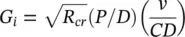
The parameter G iis plotted against ( XL ) 2in Fig. 2-19a, where XL = L / D . For a satisfactory design, it must be shown that the heat exchanger tube bundle is in the non‐resonance parts of Fig. 2-19.
2.5 Vibration Response Prediction
Due to the complexity of a multi‐span steam generator tube, a computer code is used to predict vibration response accurately and to determine the susceptibility of a tube to periodic‐wake‐shedding resonance and fluidelastic instability. Such a computer code must be capable of calculating modeshapes and natural frequencies for a number of modes at least equal to the number of tube spans.
Generally, the code will be in two parts: the first part calculates the free-vibration tube characteristics such as mode shapes and natural frequencies, while the second part is a forced vibration analysis that calculates the tube response to turbulence‐induced excitation and periodic wake shedding, and the fluidelastic instability ratios. A forced vibration analysis involves the application of the distributed flow velocities and densities that are determined using the methods outlined in Chapter 3.
From a mechanics point‐of‐view, the tubes are simply multi‐span beams clamped at the tubesheet and held at the supports with varying degrees of constraint. To predict tube response, it is convenient and appropriate to assume that the intermediate supports are hinged (or pinned). With this assumption, the analysis is linear and either a finite‐element code or an analytical code can be used, as discussed in Chapter 4.
If the tube‐to‐support clearances are too large, the tube supports will not be effective and the assumption of hinged supports will not be valid. Tube‐to‐support diametral clearances of 0.38 mm (0.015 in.) or less are typically used in nuclear heat-exchanger design. Effective supports can become ineffective if a heat exchanger is subjected to significant corrosion or a chemical cleaning technique is used to clean a fouled unit. The effects of future chemical cleaning and corrosion should be considered in the vibration response analysis.
The ultimate goal of vibration analyses is to ensure that neither fretting wear nor fatigue damage occurs in heat exchangers. Although a linear analysis does not predict fretting wear, fretting‐wear damage can be estimated, as discussed in Section 2.6.1.
Within vibration prediction codes, the tube response y ( x , t ) at any point x along the tube and at any time t may be expressed as a normal mode expansion in terms of the generalized coordinates q i (t) as follows:
(2‐44) 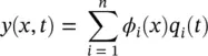
where ϕ i( x ) is the mode shape of the i thmode and n is the number of modes to be used in the analysis. Using Lagrange’s equation and assuming that the damping is small and that it does not introduce coupling between modes, the equation of motion for the i thmode is as follows:
(2‐45) 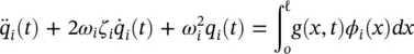
where ζ iis the damping ratio, ℓ is the tube length and ω iis the angular frequency of the i thnatural mode. The natural modes are normalized so that
(2‐46) 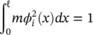
where m is the mass per unit length.
Knowing m , ζ i, the support locations and the flexural rigidity of the tube, the response to different types of forcing functions, g ( x , t ), is obtained by solving the family of equations described in Eqs. (2-44)and (2-45). Assumptions that can be used within this type of code include uniform mass distribution and flexural rigidity, negligible effect of shear and rotary inertia, no axial motion of any point along the tube, homogeneous boundary conditions and continuity at the intermediate supports.
2.5.1 Fluidelastic Instability
A fluidelastic instability ratio is determined by calculating an effective velocity based on the velocity and density profiles and the important mode shapes. For the i thmode, the critical velocity, U pc, at which instability occurs, may be expressed as:
(2‐47) 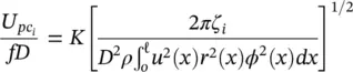
where non‐uniform flow velocities and densities are represented as U p( x ) = U p u ( x ) and ρ ( x ) = ρr ( x ) This is a generalized form of Eq. (2-25).
2.5.2 Random Turbulence Excitation
Tube response to turbulence‐induced excitation forces must be calculated using random vibration theory, and the response must be summed over all significant modes of vibration. The mean square amplitude response,  , of a continuous uniform cylindrical tube to distributed random forces, g(x,t) , may be expressed by:
(2‐48) 
where H r *and H sare complex complementary frequency response functions for the r thand s thmodes, R(x,x ′ ,f) is the spatial correlation density function and x and x ′ are points along the length of the tube. More detail is found in Pettigrew et al (1978), Axisa et al (1990) and in Chapters 9and 10.
Читать дальшеИнтервал:
Закладка:
Похожие книги на «Flow-Induced Vibration Handbook for Nuclear and Process Equipment»
Представляем Вашему вниманию похожие книги на «Flow-Induced Vibration Handbook for Nuclear and Process Equipment» списком для выбора. Мы отобрали схожую по названию и смыслу литературу в надежде предоставить читателям больше вариантов отыскать новые, интересные, ещё непрочитанные произведения.


Обсуждение, отзывы о книге «Flow-Induced Vibration Handbook for Nuclear and Process Equipment» и просто собственные мнения читателей. Оставьте ваши комментарии, напишите, что Вы думаете о произведении, его смысле или главных героях. Укажите что конкретно понравилось, а что нет, и почему Вы так считаете.