Flow-Induced Vibration Handbook for Nuclear and Process Equipment
Здесь есть возможность читать онлайн «Flow-Induced Vibration Handbook for Nuclear and Process Equipment» — ознакомительный отрывок электронной книги совершенно бесплатно, а после прочтения отрывка купить полную версию. В некоторых случаях можно слушать аудио, скачать через торрент в формате fb2 и присутствует краткое содержание. Жанр: unrecognised, на английском языке. Описание произведения, (предисловие) а так же отзывы посетителей доступны на портале библиотеки ЛибКат.
- Название:Flow-Induced Vibration Handbook for Nuclear and Process Equipment
- Автор:
- Жанр:
- Год:неизвестен
- ISBN:нет данных
- Рейтинг книги:3 / 5. Голосов: 1
-
Избранное:Добавить в избранное
- Отзывы:
-
Ваша оценка:
Flow-Induced Vibration Handbook for Nuclear and Process Equipment: краткое содержание, описание и аннотация
Предлагаем к чтению аннотацию, описание, краткое содержание или предисловие (зависит от того, что написал сам автор книги «Flow-Induced Vibration Handbook for Nuclear and Process Equipment»). Если вы не нашли необходимую информацию о книге — напишите в комментариях, мы постараемся отыскать её.
Flow-Induced Vibration Handbook for Nuclear and Process Equipment Helps readers understand and apply techniques for preventing fatigue and fretting-wear damage due to flow-induced vibration at the design stage Covers components including nuclear reactor internals, nuclear fuels, piping systems, and various types of heat exchangers Features examples of vibration-related failures caused by fatigue or fretting-wear in nuclear and process equipment Includes a detailed overview of state-of-the-art flow-induced vibration technology with an emphasis on two-phase flow-induced vibration Covering all relevant aspects of flow-induced vibration technology,
is required reading for professional mechanical engineers and researchers working in the nuclear, petrochemical, aerospace, and process industries, as well as graduate students in mechanical engineering courses on flow-induced vibration.
Flow-Induced Vibration Handbook for Nuclear and Process Equipment — читать онлайн ознакомительный отрывок
Ниже представлен текст книги, разбитый по страницам. Система сохранения места последней прочитанной страницы, позволяет с удобством читать онлайн бесплатно книгу «Flow-Induced Vibration Handbook for Nuclear and Process Equipment», без необходимости каждый раз заново искать на чём Вы остановились. Поставьте закладку, и сможете в любой момент перейти на страницу, на которой закончили чтение.
Интервал:
Закладка:
(2‐53) 
The resulting tube wall wear depth, d w, can be calculated from the wear volume. This calculation requires the relationship between d wand V . For example, for a tube within a circular hole or a scalloped bar, it may be assumed that the wear is taking place uniformly over the thickness, L , and half the circumference, D , of the support. Thus:
(2‐54a) 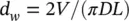
Alternately, for lattice bars and for flat bars, it may be assumed that wear is taking place only on the tubes. Thus, the bars and the wear scars remain flat. For lattice bars in the straight‐leg section, wear occurs on both sides of the tube and M = 4 in Eq. (2-54b); for flat bars in the U‐bend, we assume that wear occurs on one side of the tube and M = 8 in Eq. (2-54b). This geometry leads to
(2‐54b) 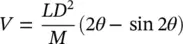
where
(2‐54c) 
Thus, the tube wall fretting‐wear depth, d w, may be estimated using Eqs. (2-53)and either (2-54a), or (2-54b)and (2-54c).
2.7 Acceptance Criteria
The flow‐induced vibration analysis should demonstrate that the heat exchanger is acceptable by satisfying the design acceptance criteria outlined below.
2.7.1 Fluidelastic Instability
The maximum flow velocity in a heat exchanger should be below the critical flow velocity for fluidelastic instability, U pc, based on a fluidelastic instability constant, K = 3.0, for liquid and two‐phase flows. Thus,
(2‐55) 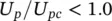
2.7.2 Random Turbulence Excitation
The vibration response to random turbulence excitation should be sufficiently low to prevent excessive tube wall reduction due to fretting wear. The tube wall fretting‐wear depth, d w, calculated as per Section 2.6.3for the entire life of the component should be less than a specified percentage of the nominal design tube wall thickness (e.g., 40%).
2.7.3 Periodic Wake Shedding
Resonance due to coincidence of tube frequency and periodic‐wake‐shedding frequency should be avoided. If the latter is not possible, the maximum (zero‐peak) tube vibration amplitude, Y max, at resonance should be less than two percent of the tube diameter, thus:
(2‐56) 
Below 0.02 D , the vibration amplitude is generally not sufficient to spatially correlate the formation of vortex shedding with the motion of the tube, thereby resulting in a much‐reduced uncorrelated vibration response.
2.7.4 Tube‐to‐Support Clearance
The tube‐to‐support clearance must be small enough to provide an effective support. Thus, pinned support conditions may be assumed provided the tube‐to‐support diametral clearance for drilled holes, broached holes, scallop bars, egg crates and lattice bars is less than or equal to 0.4 mm.
For flat‐bar‐type U‐bend supports, the vibration analysis should satisfy Section 2.7.2for the out‐of‐plane direction while assuming that one (any one) support may not be effective in the U‐bend region. In the in‐plane direction, the diametral clearance between tube and flat bar support should be sufficiently small to provide effective support (e.g., <0.1 mm).
2.7.5 Acoustic Resonance
The analysis should show that acoustic resonance conditions are avoided in the heat exchanger tube bundle. This should be based on at least two generally recognized criteria (e.g., Blevins and Bressler, 1987 and Ziada et al, 1989). The heat exchanger relevant parameter, whether it be shedding frequency, f s, acoustic frequency, f an, geometry, P/D , L/D or resonance parameter, G s, or G i, should be at least 25% away from the resonance criteria or boundary, thus:
(2‐57) 
2.7.6 Two‐Phase Flow Regimes
Flow conditions leading to intermittent flow regime should be avoided in two‐phase cross flow. This applies in particular to the U‐bend region of nuclear steam generators.
References
1 Axisa, F., Antunes, J. and Villard, B., 1990, “Random Excitation of Heat Exchanger Tubes by Cross‐Flows,” Journal of Fluid and Structures, 4, No. 3, pp. 321–341.
2 Blevins, R.D. and Bressler, M.M., 1987, “Acoustic Resonances in Heat Exchangers Part II: Prediction and Suppression of Resonance,” Journal of Pressure Vessel Technology, 109, pp. 282–288.
3 de Langre, E. and Villard, B., 1998, “An Upper Bound on Random Buffeting Forces caused by Two‐Phase Flows across Tubes,” Journal of Fluids and Structures, 12, pp. 1005–1023.
4 Grant, I.D.R., 1975, “Flow and Pressure Drop with Single Phase and Two‐Phase Flow in the Shell‐Side of Segmentally Baffled Shell‐and‐Tube Heat Exchangers,” NEL Report No. 590, National Engineering Laboratory, Glasgow, pp. 1–22.
5 Grant, I.D.R. and Chisholm, D., 1979, “Two‐Phase Flow on the Shell‐Side of a Segmentally Baffled Shell‐and‐Tube Heat Exchanger,” Journal of Heat Transfer, 101, pp. 38–42.
6 Guérout, F.M. and Fisher, N.J., 1999, “Steam Generator Fretting‐Wear Damage: A Summary of Recent Findings,” ASME Journal of Pressure Vessel Technology, 121, pp. 304–310.
7 McAdams, W.H., Woods, W.K., and Herman, L.C., 1942, “Vaporization Inside Horizontal Tubes‐II‐Benzene‐Oil Mixtures,” Trans. ASME, 64, pp. 193–200.
8 McNaught, J. M., 1982, “Two‐phase Forced Convection Heat Transfer during Condensation on Horizontal Tube Bundles,” 7th International Heat Transfer Conference, 5, Munich, pp. 125–131.
9 Owen, P.R., 1965, “Buffeting Excitation of Boiler Tube Vibration,” Journal of Mechanical Engineering Science, 7, pp. 431–439.
10 Pettigrew, M.J. and Gorman, D.J., 1981, “Vibration of Heat Exchanger Tube Bundles in Liquid and Two‐Phase Cross‐Flow,” Proceedings of the ASME Pressure Vessel and Piping Conference, San Francisco, California, 1980 August, Vol. 52, pp. 89–110.
11 Pettigrew, M.J. and Taylor, C.E., 1991, “Fluidelastic Instability of Heat Exchanger Tube Bundles: Review and Design Recommendations,” ASME Journal of Pressure Vessel Technology, 113, pp. 242–256.
12 Pettigrew, M.J. and Taylor, C.E., 1994, “Two‐Phase Flow‐Induced Vibration: An Overview,” ASME Journal of Pressure Vessel Technology, 116, pp. 233–253.
Читать дальшеИнтервал:
Закладка:
Похожие книги на «Flow-Induced Vibration Handbook for Nuclear and Process Equipment»
Представляем Вашему вниманию похожие книги на «Flow-Induced Vibration Handbook for Nuclear and Process Equipment» списком для выбора. Мы отобрали схожую по названию и смыслу литературу в надежде предоставить читателям больше вариантов отыскать новые, интересные, ещё непрочитанные произведения.


Обсуждение, отзывы о книге «Flow-Induced Vibration Handbook for Nuclear and Process Equipment» и просто собственные мнения читателей. Оставьте ваши комментарии, напишите, что Вы думаете о произведении, его смысле или главных героях. Укажите что конкретно понравилось, а что нет, и почему Вы так считаете.