Flow-Induced Vibration Handbook for Nuclear and Process Equipment
Здесь есть возможность читать онлайн «Flow-Induced Vibration Handbook for Nuclear and Process Equipment» — ознакомительный отрывок электронной книги совершенно бесплатно, а после прочтения отрывка купить полную версию. В некоторых случаях можно слушать аудио, скачать через торрент в формате fb2 и присутствует краткое содержание. Жанр: unrecognised, на английском языке. Описание произведения, (предисловие) а так же отзывы посетителей доступны на портале библиотеки ЛибКат.
- Название:Flow-Induced Vibration Handbook for Nuclear and Process Equipment
- Автор:
- Жанр:
- Год:неизвестен
- ISBN:нет данных
- Рейтинг книги:3 / 5. Голосов: 1
-
Избранное:Добавить в избранное
- Отзывы:
-
Ваша оценка:
Flow-Induced Vibration Handbook for Nuclear and Process Equipment: краткое содержание, описание и аннотация
Предлагаем к чтению аннотацию, описание, краткое содержание или предисловие (зависит от того, что написал сам автор книги «Flow-Induced Vibration Handbook for Nuclear and Process Equipment»). Если вы не нашли необходимую информацию о книге — напишите в комментариях, мы постараемся отыскать её.
Flow-Induced Vibration Handbook for Nuclear and Process Equipment Helps readers understand and apply techniques for preventing fatigue and fretting-wear damage due to flow-induced vibration at the design stage Covers components including nuclear reactor internals, nuclear fuels, piping systems, and various types of heat exchangers Features examples of vibration-related failures caused by fatigue or fretting-wear in nuclear and process equipment Includes a detailed overview of state-of-the-art flow-induced vibration technology with an emphasis on two-phase flow-induced vibration Covering all relevant aspects of flow-induced vibration technology,
is required reading for professional mechanical engineers and researchers working in the nuclear, petrochemical, aerospace, and process industries, as well as graduate students in mechanical engineering courses on flow-induced vibration.
Flow-Induced Vibration Handbook for Nuclear and Process Equipment — читать онлайн ознакомительный отрывок
Ниже представлен текст книги, разбитый по страницам. Система сохранения места последней прочитанной страницы, позволяет с удобством читать онлайн бесплатно книгу «Flow-Induced Vibration Handbook for Nuclear and Process Equipment», без необходимости каждый раз заново искать на чём Вы остановились. Поставьте закладку, и сможете в любой момент перейти на страницу, на которой закончили чтение.
Интервал:
Закладка:
(2‐23) 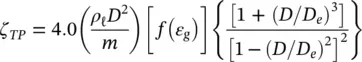
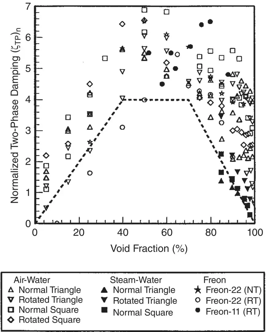
Fig. 2-10 Comparison Between Proposed Design Guideline and Available Damping Data. Normalized Two‐Phase Damping Ratio ( ζ TP) n:
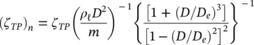
As shown in Fig. 2-10, the void‐fraction function, f ( ε g), may be approximated by taking the envelope through the lower decile of the data:
(2‐24) 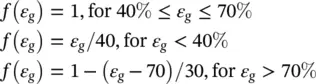
The fluid properties/flow regime dependence was difficult to assess in the absence of a broad range of damping data for different two‐phase mixtures. Flow regime effects are partly taken care of by the void‐fraction function.
Tube fouling is not expected to contribute much to damping. However, support damping is considerably reduced by crudding within the support. At the limit, when tubes are jammed in the support by severe crud deposition, a support damping value of ζ S= 0.2% should be used in analysis.
Dynamic Stiffness and Support Effectiveness The dynamic stiffness of multi‐span heat exchanger tubes is simply the flexural rigidity, EI , where E is the elastic modulus of the tube material and I is the area moment of inertia of the tube cross‐section. The boundary conditions, that is, the support conditions, are somewhat complex. The tubes are effectively clamped at the tubesheet. To facilitate assembly and to allow for thermal expansion, there is a clearance between tubes and tube supports. The diametral clearance between tube and intermediate support is typically 0.25 to 0.80 mm (for many nuclear heat exchangers, the diametral clearance is specified to be 0.38 mm or 0.015 in.). Thus, the dynamic interaction between tube and tube support is inherently non‐linear. In well‐designed heat exchangers, the tube vibration response at mid‐span is mostly less than 100 μ m root‐mean‐square (rms) and much less at the supports (usually less than 25 μ m rms). This response is significantly less than the available diametral clearance. Thus, the tubes do not generally vibrate back and forth across the available clearance. Instead, most tubes are not centered within the supports and are, therefore, contacting or vibrating very close to one side of the supports. It is difficult to imagine that many tubes of typically one‐metre span length, would be located concentrically within a 0.38 mm diametral clearance without touching the support. The chances of a tube not touching a support are probably much less than one percent. Thus, it is reasonable to assume pinned conditions at the supports to allow for a quasi‐linear vibration analysis. For the purpose of vibration analysis, drilled hole, broached hole, and egg‐crate type supports may be taken as pinned supports.
Anti‐vibration bars (AVBs) are often used in the U‐bend region of nuclear steam generators. AVBs are reasonably effective in the out‐of‐plane direction, but offer little restraint in the in‐plane (plane of the U‐bend) direction (Taylor et al, 1995). Fortunately, the vibration response is usually much less in the in‐plane direction than in the out‐of‐plane direction. Nevertheless, AVBs are less effective than other clearance supports. For steam generator vibration analyses, it is recommended that one (any one) AVB in the U‐bend region be assumed ineffective. The possibility that two adjacent AVBs would be ineffective at the same time is considered too improbable to be of concern. For example, if we assume that the probability of one AVB being ineffective is less than one percent, then the probability of two adjacent AVBs being ineffective is less than 0.01% or less than one tube in 10 000, which is less than one tube per steam generator and, thus, insignificant.
In the in‐plane direction, on the other hand, recent experience has shown that more than one adjacent AVB may be ineffective and that maybe two or more AVBs should be assumed ineffective in the in‐plane direction. In practice, tube‐to‐support clearances must be small enough to provide an effective support. Thus, pinned support conditions may be assumed provided that the tube‐to‐support diametral clearance for drilled holes, broached holes, scallop bars, egg crates and lattice bars is equal to or less than 0.4 mm. In the out‐of‐plane direction, the diametral clearance between tube and AVBs should be sufficiently small to provide effective support (e.g., <0.1 mm).
2.4 Vibration Excitation Mechanisms
As mentioned previously in Section 2.1.1, several vibration mechanisms are normally considered in heat exchange components: fluidelastic instability, random turbulence excitation, periodic wake shedding and acoustic resonance. Formulations for these mechanisms are presented in the following sub‐sections ( Sections 2.4.1to 2.4.5) of this chapter. More details are given in Chapters 7to 11.
2.4.1 Fluidelastic Instability
Fluidelastic instability is the most severe vibration excitation mechanism in heat exchanger tube bundles. Formulations for single‐ and two‐phase cross flow are given below. The topics are discussed in more detail in Chapters 7and 8for single‐ and two‐phase flow, respectively.
Single‐Phase Cross Flow (Gas or Liquid)
Fluidelastic instability for tube bundles subjected to single‐phase cross flow was reviewed by Pettigrew and Taylor (1991). Fluidelastic instability is formulated in terms of a dimensionless flow velocity, U p/ fD and a dimensionless mass‐damping parameter, 2 πζm / ρD 2, such that:
(2‐25) 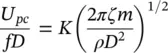
where f is the tube natural frequency, ρ is the fluid density, m is the tube mass per unit length and U pcis the threshold, or critical, flow velocity for fluidelastic instability. A fluidelastic instability constant K = 3.0 is recommended for all tube bundle configurations, as shown in Fig. 2-11(Pettigrew and Taylor, 1991). The damping ratio, ζ , is the total damping ratio as outlined in Section 2.3.2. The above formulation applies to all cross‐flow regions such as steam generator preheater regions, heat‐exchanger tube bundles between baffle plates, and outlet and inlet regions.
Two‐Phase Flow
We have found that fluidelastic instability behavior is somewhat similar in continuous two‐phase cross flow, (Pettigrew et al, 1989b). As explained in Chapter 3, continuous flow means two‐phase flow regions of a continuous nature such as bubbly, spray, fog and wall flows as opposed to intermittent flow regimes leading to bundle reflooding and large flow oscillations. Such oscillations can lead to much lower critical velocity for fluidelastic instability (Pettigrew et al, 1989b, 1995 and 1994). Thus, intermittent flow regimes should be avoided in two‐phase cross flow.
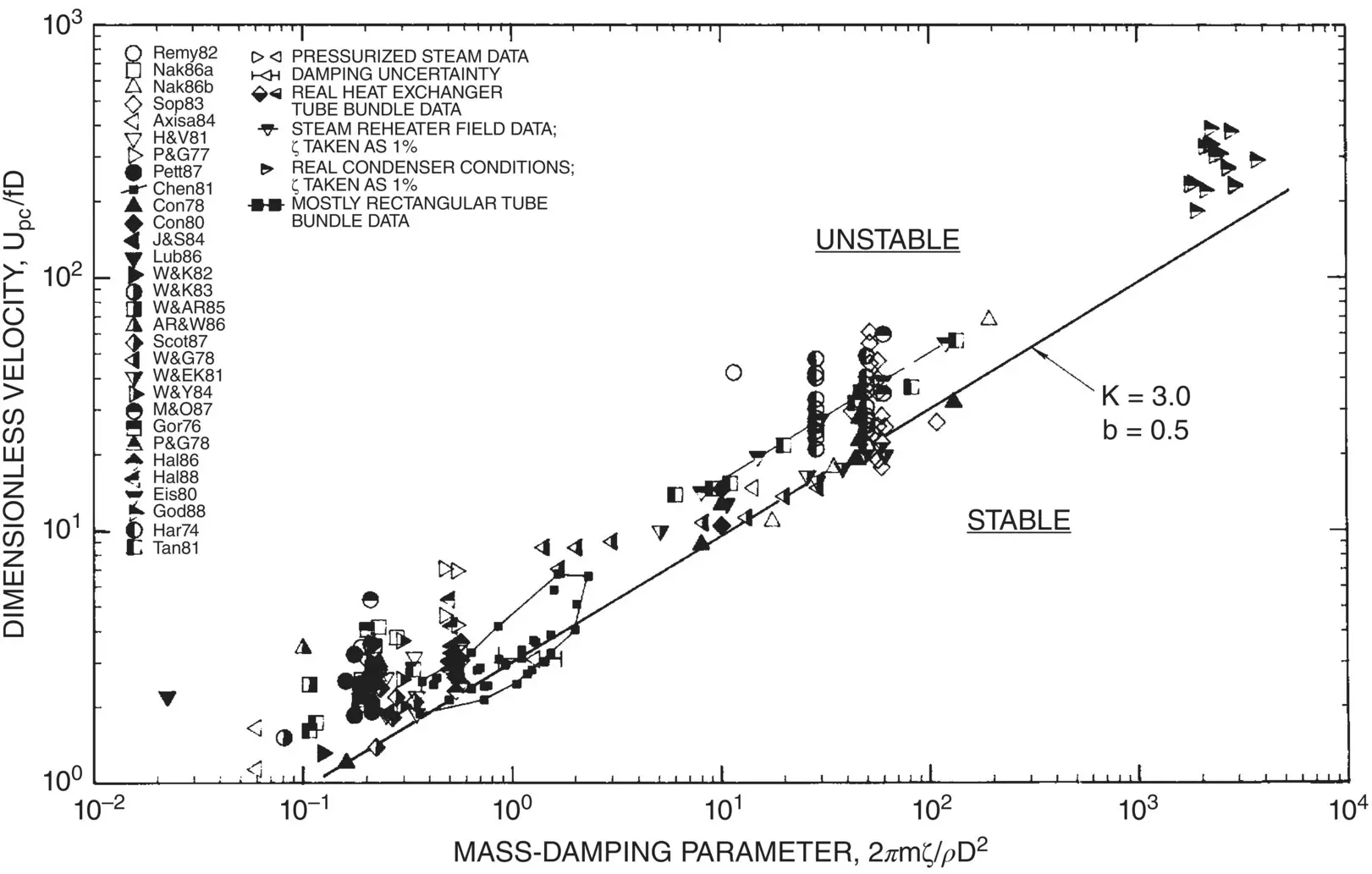
Fig. 2-11 Summary of Fluidelastic Instability Data for Single‐Phase Cross Flow: Recommended Design Guidelines.
Читать дальшеИнтервал:
Закладка:
Похожие книги на «Flow-Induced Vibration Handbook for Nuclear and Process Equipment»
Представляем Вашему вниманию похожие книги на «Flow-Induced Vibration Handbook for Nuclear and Process Equipment» списком для выбора. Мы отобрали схожую по названию и смыслу литературу в надежде предоставить читателям больше вариантов отыскать новые, интересные, ещё непрочитанные произведения.


Обсуждение, отзывы о книге «Flow-Induced Vibration Handbook for Nuclear and Process Equipment» и просто собственные мнения читателей. Оставьте ваши комментарии, напишите, что Вы думаете о произведении, его смысле или главных героях. Укажите что конкретно понравилось, а что нет, и почему Вы так считаете.