Flow-Induced Vibration Handbook for Nuclear and Process Equipment
Здесь есть возможность читать онлайн «Flow-Induced Vibration Handbook for Nuclear and Process Equipment» — ознакомительный отрывок электронной книги совершенно бесплатно, а после прочтения отрывка купить полную версию. В некоторых случаях можно слушать аудио, скачать через торрент в формате fb2 и присутствует краткое содержание. Жанр: unrecognised, на английском языке. Описание произведения, (предисловие) а так же отзывы посетителей доступны на портале библиотеки ЛибКат.
- Название:Flow-Induced Vibration Handbook for Nuclear and Process Equipment
- Автор:
- Жанр:
- Год:неизвестен
- ISBN:нет данных
- Рейтинг книги:3 / 5. Голосов: 1
-
Избранное:Добавить в избранное
- Отзывы:
-
Ваша оценка:
Flow-Induced Vibration Handbook for Nuclear and Process Equipment: краткое содержание, описание и аннотация
Предлагаем к чтению аннотацию, описание, краткое содержание или предисловие (зависит от того, что написал сам автор книги «Flow-Induced Vibration Handbook for Nuclear and Process Equipment»). Если вы не нашли необходимую информацию о книге — напишите в комментариях, мы постараемся отыскать её.
Flow-Induced Vibration Handbook for Nuclear and Process Equipment Helps readers understand and apply techniques for preventing fatigue and fretting-wear damage due to flow-induced vibration at the design stage Covers components including nuclear reactor internals, nuclear fuels, piping systems, and various types of heat exchangers Features examples of vibration-related failures caused by fatigue or fretting-wear in nuclear and process equipment Includes a detailed overview of state-of-the-art flow-induced vibration technology with an emphasis on two-phase flow-induced vibration Covering all relevant aspects of flow-induced vibration technology,
is required reading for professional mechanical engineers and researchers working in the nuclear, petrochemical, aerospace, and process industries, as well as graduate students in mechanical engineering courses on flow-induced vibration.
Flow-Induced Vibration Handbook for Nuclear and Process Equipment — читать онлайн ознакомительный отрывок
Ниже представлен текст книги, разбитый по страницам. Система сохранения места последней прочитанной страницы, позволяет с удобством читать онлайн бесплатно книгу «Flow-Induced Vibration Handbook for Nuclear and Process Equipment», без необходимости каждый раз заново искать на чём Вы остановились. Поставьте закладку, и сможете в любой момент перейти на страницу, на которой закончили чтение.
Интервал:
Закладка:
(2‐15) 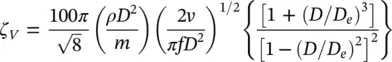
where v is the kinematic viscosity of the fluid and f is the natural frequency of the tube for the mode being analysed. Clearly, viscous damping is frequency dependent. Calculated values of damping using Eq. (2-15)are compared against experimental data in Fig. 2-7. The comparison shows reasonable agreement.
Squeeze‐film damping, ζ SF, and friction damping, ζ F, take place at the supports. Semi‐empirical expressions were developed, based on available experimental data, to formulate friction and squeeze‐film damping as discussed by Pettigrew et al (2011) and in Chapter 5. The available experimental data is outlined in Fig. 2-8. Thus, squeeze‐film damping (in percent) may be formulated by
(2‐16) 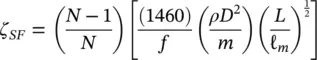
and friction damping (in percent) by
(2‐17) 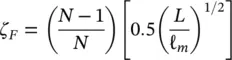
where ( N − 1)/ N takes into account the ratio of the number of supports over the number of spans, L is the support thickness and ℓ mis a characteristic tube length. The latter is defined as the average of the three longest spans when the lowest modes and the longest spans dominate the vibration response. This is usually the case. When higher modes and shorter spans govern the vibration response, then, the characteristic span length should be based on these shorter spans. This could happen when there are high flow velocities locally, such as in entrance or exit regions.
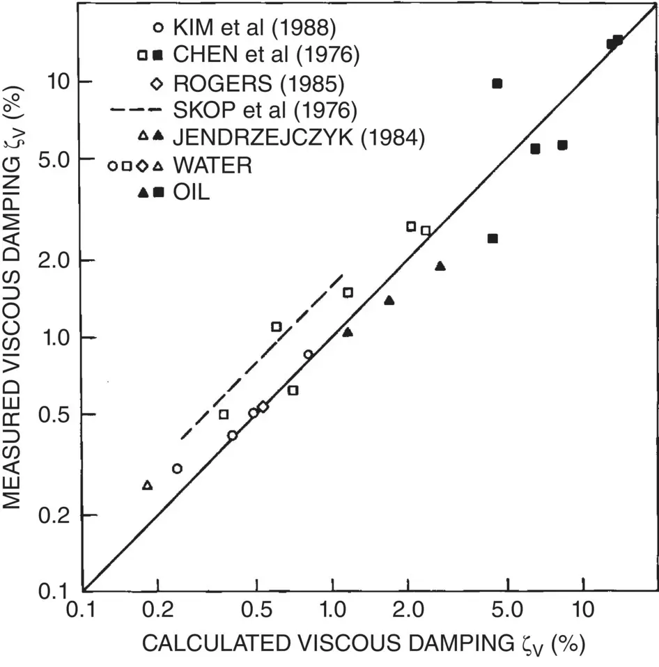
Fig. 2-7 Viscous Damping Data for a Cylinder in Unconfined and Confined Liquids: Comparison Between Theory and Experiment.
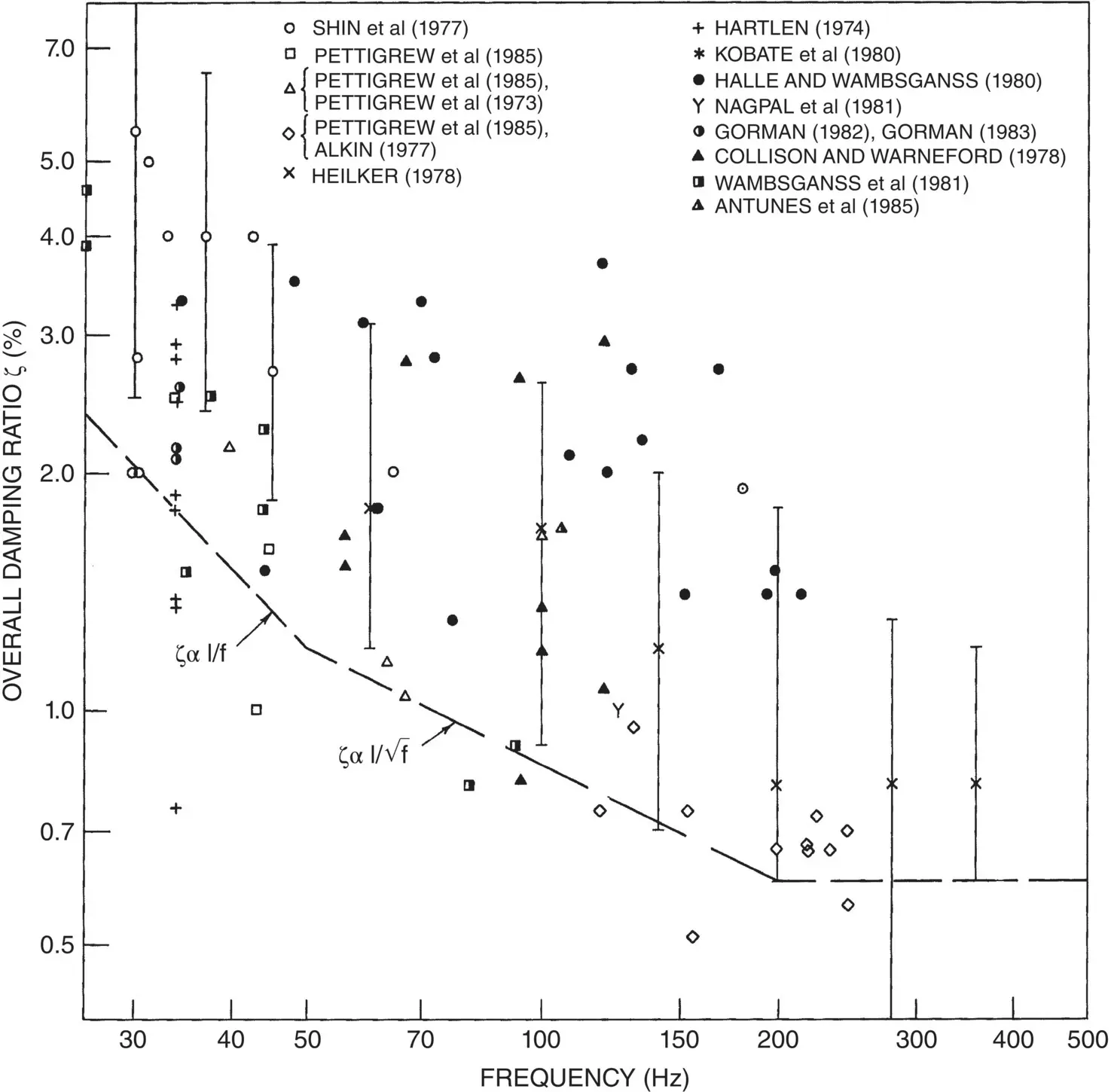
Fig. 2-8 Damping Data for Multi‐Span Heat Exchanger Tubes in Water.
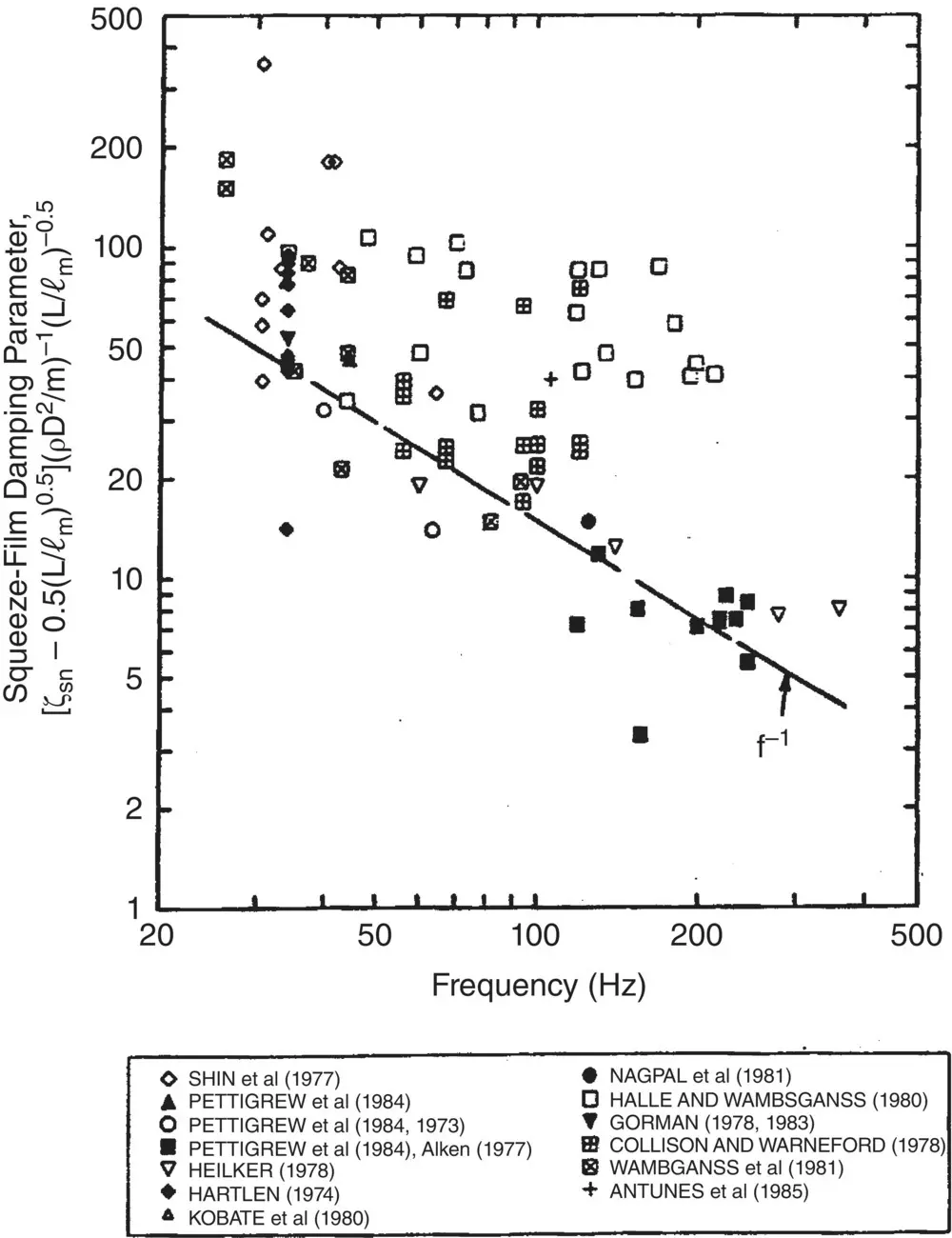
Fig. 2-9 Comparison Between Tube Support Damping Model (Squeeze‐Film and Friction) and Experimental Data.
Equations (2-16)and (2-17)are combined to determine the squeeze‐film damping parameter, 1460/ f , and compared against available experimental data in Fig. 2-9. There is large scatter in the data, which is mostly due to the nature of the problem. Heat exchanger tube damping depends on parameters that are difficult to control, such as support alignment, tube straightness, relative position of tube within the support, and side loads. These parameters are statistical in nature and probably contribute to much of the scatter. A conservative but realistic criterion for damping is obtained by taking damping values at roughly the lower decile of the available data, as shown in Fig. 2-8.
Substituting Eqs. (2-15), (2-16)and (2-17)in Eq. (2-14):
(2‐18) 
Although somewhat speculative, Eq. (2-18)formulates all important energy dissipation mechanisms and fits the data best. Thus, it is our recommendation as a damping criterion for design purposes.
However, if the damping ratio predicted by this equation is less than 0.6%, we recommend taking a minimum value of 0.6%. As shown in Fig. 2-8, a minimum damping of 0.6% appears reasonable. In Fig. 2-8, there is no experimental data for frequencies below 25 Hz. Rather than extrapolating Eq. 2-18to lower frequencies, we recommend using a maximum total damping of 5%.
Damping in Two‐Phase Flow
The subject of heat exchanger tube damping in two‐phase flow was reviewed by Pettigrew and Taylor (1997) as discussed in Chapter 6. The total damping ratio, ζ T, of a multi‐span heat exchanger tube in two‐phase flow comprises support damping, ζ S, viscous damping, ζ V, and two‐phase damping, ζ TP:
(2‐19) 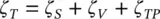
Depending on the thermalhydraulic conditions (i.e., heat flux, void fraction, flow, etc.), the supports may be dry or wet. If the supports are dry, which is more likely for high heat flux and very high void fraction, only friction damping takes place. Support damping in this case is analogous to damping of heat exchanger tubes in gases, Pettigrew et al (1986). Damping due to friction (and impact) in dry supports may be expressed by Eq. (2-13). The above situation is unlikely in well‐designed recirculating steam generators. However, it could exist in some areas of once‐through steam generators.
When there is liquid between the tube and the support, support damping includes both squeeze‐film damping, ζ SF, and friction damping, ζ F. This situation is analogous to heat exchanger tubes in liquids and the support damping may be evaluated with Eqs. (2.18) and (2.19) above:
(2‐20) 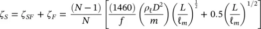
Note that in Eq. (2-20), ρ ℓis the density of the liquid within the tube support, whereas m is the total mass per unit length of the tube including the hydrodynamic mass calculated with the two‐phase homogeneous density.
Viscous damping in two‐phase mixtures is analogous to viscous damping in single‐phase fluids (Pettigrew and Taylor, 1997). Homogeneous properties of the two‐phase mixture are used in its formulation, as follows:
(2‐21) 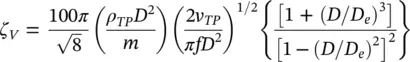
where v TPis the equivalent two‐phase kinematic viscosity as per McAdams et al (1942):
(2‐22) 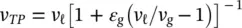
Above 40% void fraction, viscous damping is generally small and could be neglected for the U‐bend region of steam generators. However, it is significant for lower void fractions.
There is a two‐phase component of damping in addition to viscous damping. As discussed by Pettigrew and Taylor (1997) and in Chapter 6, two‐phase damping is strongly dependent on void fraction, fluid properties and flow regimes, directly related to confinement and the ratio of hydrodynamic mass over tube mass, and weakly related to frequency, mass flux or flow velocity, and tube bundle configuration. A semi‐empirical expression was developed from the available experimental data to formulate the two‐phase component of damping, ζ TP, in percent:
Читать дальшеИнтервал:
Закладка:
Похожие книги на «Flow-Induced Vibration Handbook for Nuclear and Process Equipment»
Представляем Вашему вниманию похожие книги на «Flow-Induced Vibration Handbook for Nuclear and Process Equipment» списком для выбора. Мы отобрали схожую по названию и смыслу литературу в надежде предоставить читателям больше вариантов отыскать новые, интересные, ещё непрочитанные произведения.


Обсуждение, отзывы о книге «Flow-Induced Vibration Handbook for Nuclear and Process Equipment» и просто собственные мнения читателей. Оставьте ваши комментарии, напишите, что Вы думаете о произведении, его смысле или главных героях. Укажите что конкретно понравилось, а что нет, и почему Вы так считаете.