Flow-Induced Vibration Handbook for Nuclear and Process Equipment
Здесь есть возможность читать онлайн «Flow-Induced Vibration Handbook for Nuclear and Process Equipment» — ознакомительный отрывок электронной книги совершенно бесплатно, а после прочтения отрывка купить полную версию. В некоторых случаях можно слушать аудио, скачать через торрент в формате fb2 и присутствует краткое содержание. Жанр: unrecognised, на английском языке. Описание произведения, (предисловие) а так же отзывы посетителей доступны на портале библиотеки ЛибКат.
- Название:Flow-Induced Vibration Handbook for Nuclear and Process Equipment
- Автор:
- Жанр:
- Год:неизвестен
- ISBN:нет данных
- Рейтинг книги:3 / 5. Голосов: 1
-
Избранное:Добавить в избранное
- Отзывы:
-
Ваша оценка:
Flow-Induced Vibration Handbook for Nuclear and Process Equipment: краткое содержание, описание и аннотация
Предлагаем к чтению аннотацию, описание, краткое содержание или предисловие (зависит от того, что написал сам автор книги «Flow-Induced Vibration Handbook for Nuclear and Process Equipment»). Если вы не нашли необходимую информацию о книге — напишите в комментариях, мы постараемся отыскать её.
Flow-Induced Vibration Handbook for Nuclear and Process Equipment Helps readers understand and apply techniques for preventing fatigue and fretting-wear damage due to flow-induced vibration at the design stage Covers components including nuclear reactor internals, nuclear fuels, piping systems, and various types of heat exchangers Features examples of vibration-related failures caused by fatigue or fretting-wear in nuclear and process equipment Includes a detailed overview of state-of-the-art flow-induced vibration technology with an emphasis on two-phase flow-induced vibration Covering all relevant aspects of flow-induced vibration technology,
is required reading for professional mechanical engineers and researchers working in the nuclear, petrochemical, aerospace, and process industries, as well as graduate students in mechanical engineering courses on flow-induced vibration.
Flow-Induced Vibration Handbook for Nuclear and Process Equipment — читать онлайн ознакомительный отрывок
Ниже представлен текст книги, разбитый по страницам. Система сохранения места последней прочитанной страницы, позволяет с удобством читать онлайн бесплатно книгу «Flow-Induced Vibration Handbook for Nuclear and Process Equipment», без необходимости каждый раз заново искать на чём Вы остановились. Поставьте закладку, и сможете в любой момент перейти на страницу, на которой закончили чтение.
Интервал:
Закладка:
2.1.2 Scope of a Vibration Analysis
A heat exchanger vibration analysis consists of the following steps: 1) flow distribution calculations, 2) dynamic parameter evaluation (i.e., damping, effective tube mass, and dynamic stiffness), 3) formulation of vibration excitation mechanisms, 4) vibration response prediction, and 5) resulting damage assessment (i.e., comparison against allowables). The requirements applicable to each step are outlined in this overview. Each step is discussed in more detail in the following chapters of this handbook.
2.2 Flow Calculations
Flow‐induced vibration problems usually occur on a small number of vulnerable tubes in specific areas of a component (e.g., piping elements, entrance regions and tube‐free lanes in heat exchangers, and U‐tubes in nuclear steam generators). Thus, a flow analysis is required to obtain the local flow conditions throughout these heat exchange components. Flow considerations are discussed in detail in Chapter 3.
2.2.1 Flow Parameter Definition
The end results of a flow analysis are the shell‐side cross‐flow velocity, U p, and fluid density, ρ , distributions along critical tubes. For flow‐induced vibration analyses, flow velocity is defined in terms of the pitch velocity:
(2‐1) 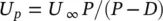
where U ∞is the free stream velocity (i.e., the velocity that would prevail if the tubes were removed), P is the pitch between the tubes and D is the tube diameter. For finned tubes, the equivalent or effective diameter, D eff, is used. The pitch velocity is sometimes called the reference gap velocity. The pitch velocity is a convenient definition since it applies to all bundle configurations.
The situation is somewhat more complex in two‐phase flow. Another parameter, steam quality or void fraction, is required to define the flow conditions. Two‐phase mixtures are rarely homogeneous or uniform across a flow path. However, it is convenient and simple to use homogeneous two‐phase mixture properties as they are well defined. This is done consistently here for both specifying vibration guidelines and formulating vibration mechanisms. The homogeneous void fraction, ε g, is defined in terms of the volume flow rates of gas,  , and liquid,
  as:
as:
(2‐2) 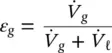
The homogeneous density, ρ , the free stream velocity, U ∞, and the free stream mass flux,  are defined using the homogeneous void fraction:
(2‐3) 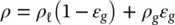
(2‐4) 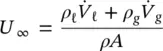
(2‐5) 
where ρg and ρℓ are the densities of the gas and liquid phase, respectively, and A is the free‐stream flow path area.
For both liquid and two‐phase cross flow, the pitch velocity, U p, and the pitch mass flux,  , are similarly defined as:
(2‐6) 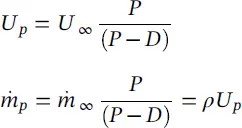
2.2.2 Simple Flow Path Approach
For relatively simple components, where the flow paths are reasonably well defined, a flow path approach may be adequate to calculate flow velocities, as illustrated in Fig. 2-1. In the flow path analysis approach, characteristic flow paths (i.e., through the tube bundle, between the tube bundle and shell, etc.) between regions of common pressures are identified. Flow impedances (i.e., pressure drop coefficients) are estimated. The flows within each path are then calculated. The resulting flow velocity distributions are then used to estimate vibration excitation mechanisms and predict vibration response.
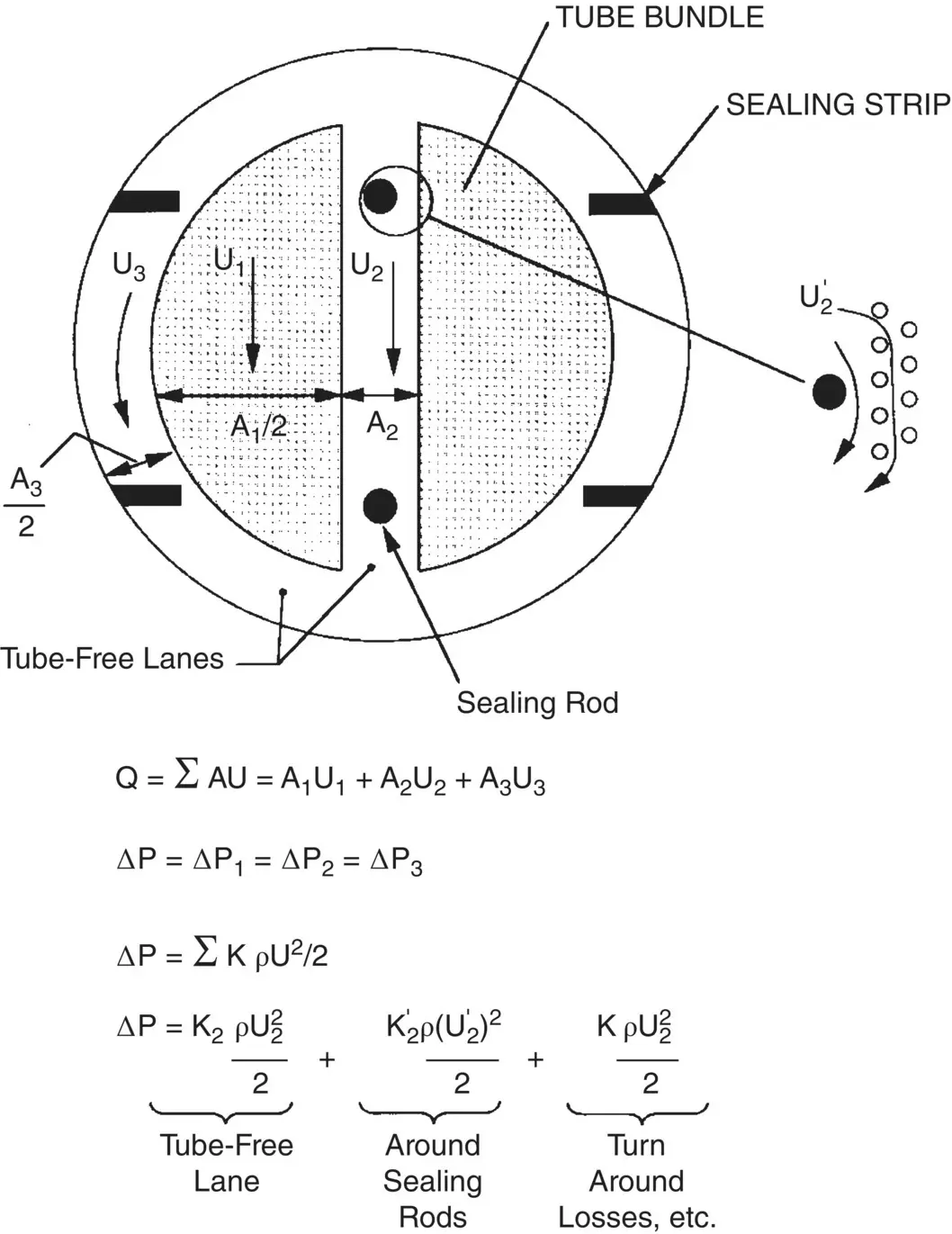
Fig. 2-1 Flow‐Path Approach.
All typical operating conditions must be considered including the following: 1) as‐designed operating conditions, from zero to 100% flow, 2) operating conditions with fouling of the tubes or crudding of the tube supports, and 3) other possible operating conditions (e.g., after chemical cleaning, system testing, etc.).
Fig. 2-2 Thermalhydraulic Analysis: Axial Grid Layout for a Typical Steam Generator with Preheater (Distances in Metres).
2.2.3 Comprehensive 3‐D Approach
For complex components such as nuclear steam generators and power condensers, a comprehensive three‐dimensional thermalhydraulic analysis is required. In such analyses, the component is divided into a large number of control volumes. The equations of energy, momentum and continuity are solved for each control volume. This is done with numerical methods using a computer code such as the THIRST code for steam generators (Pietralik, 1995). The numerical grid outlining the control volumes for the analysis of a typical steam generator is shown in Fig. 2-2. The grid must be sufficiently fine to accurately predict the flow distribution along the tube. Some typical thermalhydraulic analysis results are shown in Fig. 2-3for the U‐bend region of a steam generator. For flow‐induced vibration analyses, the results must be in the form of pitch flow velocity and fluid density distributions along a given tube. These distributions constitute the input to a flow‐induced vibration analysis of this particular tube. Figure 2-4shows pitch flow velocity and fluid density distributions for an example condenser tube.
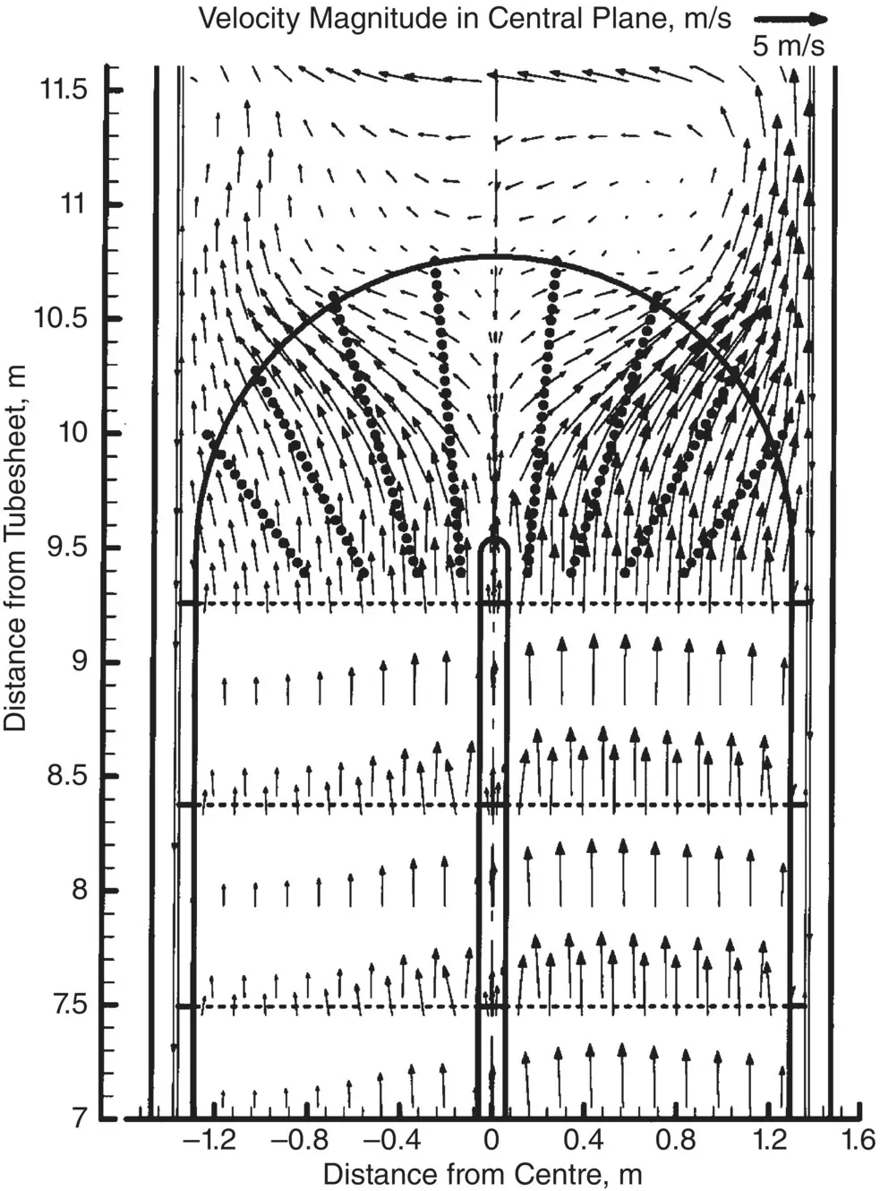
Fig. 2-3 Flow Velocity Vectors in the Central Plane of a Typical Steam Generator U‐Bend Region.
Читать дальшеИнтервал:
Закладка:
Похожие книги на «Flow-Induced Vibration Handbook for Nuclear and Process Equipment»
Представляем Вашему вниманию похожие книги на «Flow-Induced Vibration Handbook for Nuclear and Process Equipment» списком для выбора. Мы отобрали схожую по названию и смыслу литературу в надежде предоставить читателям больше вариантов отыскать новые, интересные, ещё непрочитанные произведения.


Обсуждение, отзывы о книге «Flow-Induced Vibration Handbook for Nuclear and Process Equipment» и просто собственные мнения читателей. Оставьте ваши комментарии, напишите, что Вы думаете о произведении, его смысле или главных героях. Укажите что конкретно понравилось, а что нет, и почему Вы так считаете.