Flow-Induced Vibration Handbook for Nuclear and Process Equipment
Здесь есть возможность читать онлайн «Flow-Induced Vibration Handbook for Nuclear and Process Equipment» — ознакомительный отрывок электронной книги совершенно бесплатно, а после прочтения отрывка купить полную версию. В некоторых случаях можно слушать аудио, скачать через торрент в формате fb2 и присутствует краткое содержание. Жанр: unrecognised, на английском языке. Описание произведения, (предисловие) а так же отзывы посетителей доступны на портале библиотеки ЛибКат.
- Название:Flow-Induced Vibration Handbook for Nuclear and Process Equipment
- Автор:
- Жанр:
- Год:неизвестен
- ISBN:нет данных
- Рейтинг книги:3 / 5. Голосов: 1
-
Избранное:Добавить в избранное
- Отзывы:
-
Ваша оценка:
Flow-Induced Vibration Handbook for Nuclear and Process Equipment: краткое содержание, описание и аннотация
Предлагаем к чтению аннотацию, описание, краткое содержание или предисловие (зависит от того, что написал сам автор книги «Flow-Induced Vibration Handbook for Nuclear and Process Equipment»). Если вы не нашли необходимую информацию о книге — напишите в комментариях, мы постараемся отыскать её.
Flow-Induced Vibration Handbook for Nuclear and Process Equipment Helps readers understand and apply techniques for preventing fatigue and fretting-wear damage due to flow-induced vibration at the design stage Covers components including nuclear reactor internals, nuclear fuels, piping systems, and various types of heat exchangers Features examples of vibration-related failures caused by fatigue or fretting-wear in nuclear and process equipment Includes a detailed overview of state-of-the-art flow-induced vibration technology with an emphasis on two-phase flow-induced vibration Covering all relevant aspects of flow-induced vibration technology,
is required reading for professional mechanical engineers and researchers working in the nuclear, petrochemical, aerospace, and process industries, as well as graduate students in mechanical engineering courses on flow-induced vibration.
Flow-Induced Vibration Handbook for Nuclear and Process Equipment — читать онлайн ознакомительный отрывок
Ниже представлен текст книги, разбитый по страницам. Система сохранения места последней прочитанной страницы, позволяет с удобством читать онлайн бесплатно книгу «Flow-Induced Vibration Handbook for Nuclear and Process Equipment», без необходимости каждый раз заново искать на чём Вы остановились. Поставьте закладку, и сможете в любой момент перейти на страницу, на которой закончили чтение.
Интервал:
Закладка:
2.5.3 Periodic Wake Shedding
The response to periodic wake shedding must be calculated for any modes that are found to have Strouhal numbers in the range defined in Section 2.4.3. Assuming that the damping is small, peak vibration amplitudes, Y(x) , at resonance for the i thmode may be expressed as:
(2‐49) 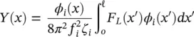
where F L( x ′) is a distributed periodic force formulated by:
(2‐50) 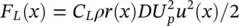
where C Lis the dynamic lift coefficient defined in Section 2.4.3. Equation (2-50)is a generalized form of Eq. (2-35).
Periodic wake shedding can result from very localized flow over a single span. If the velocity distribution has large step changes in velocity, an effective velocity approach like that used for calculating fluidelastic instability may not be appropriate for periodic wake shedding. Regions with nozzles and inlets may have to be assessed separately.
2.5.4 Acoustic Resonance
Susceptibility to acoustic resonance is not assessed by calculating the tube response. It is estimated by the method described in Sections 2.4.4and 2.4.5.
2.5.5 Example of Vibration Analysis
An example of a vibration analysis for a typical heat exchanger U‐tube is illustrated in Figs. . This vibration analysis was done with the heat exchanger vibration analysis code PIPO1.
The tube support geometry and the support locations are shown in Fig. 2-20. The input data required for the PIPO1 code is outlined in Fig. 2-21. This figure shows the thermalhydraulic input in the form of pitch flow velocity distribution along the tube. Note the relatively high flow velocity in the inlet region near the tubesheet.

Fig. 2-20 Flow Velocities, Support Locations and Tube Geometry for a Typical Heat Exchanger Tube.
Fig. 2-21 Example of Heat Exchanger Tube Vibration Analysis: Input of Vibration Analysis Code PIPO1.
Typical free vibration analysis results are shown in Fig. 2-22for selected vibration modes. The results include the vibration mode shapes and the natural frequencies.
Figure 2-23shows the results of a fluidelastic instability analysis for the condenser tube described in Fig. 2-4. For some vibration modes, the ratio of actual to critical flow velocity for fluidelastic instability, U p/ U pc, is greater than one, indicating that fluidelastic instability is possible for this tube, which was subjected to abnormal flow conditions. In reality, fretting‐wear and fatigue damage were observed in this condenser.
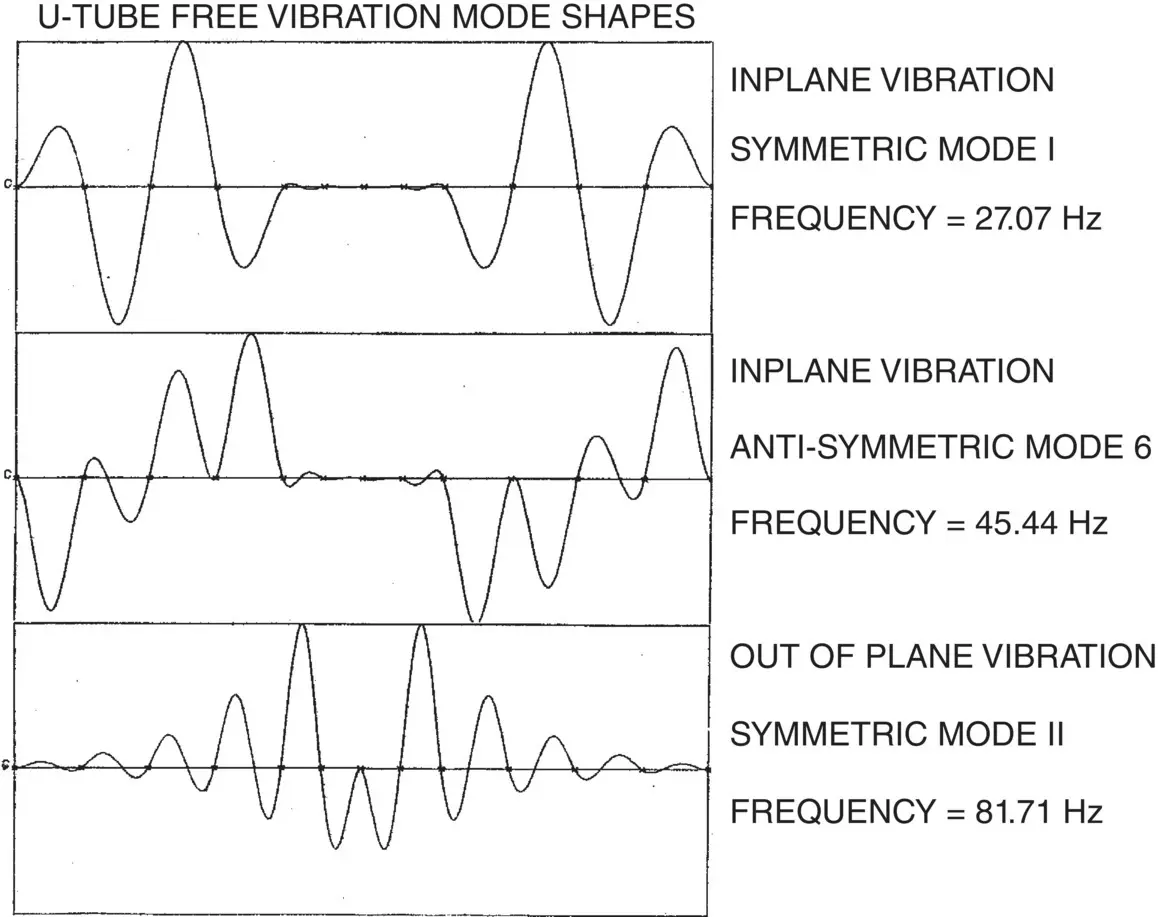
Fig. 2-22 Heat Exchanger Tube Vibration: Typical Free Vibration Analysis Results.
2.6 Fretting‐Wear Damage Considerations
Fretting‐wear damage may be assessed using the following methodology, as discussed in detail in Chapter 12. The total fretting‐wear damage over the life of the heat exchanger must not exceed the allowable tube wall reduction or wear depth, d w.
2.6.1 Fretting‐Wear Assessment
Fretting‐wear damage may be estimated using the following modified Archard equation:
(2‐51) 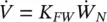
where  is the volume fretting‐wear rate, K FWis the fretting‐wear coefficient, and
  is the normal work‐rate. Work‐rate is the available mechanical energy from the dynamic interaction between tube and support and is an appropriate parameter to predict fretting‐wear damage. Work‐rate may be calculated by performing a non‐linear time domain simulation of a multi‐span heat exchanger tube vibrating within its supports (Yetisir and Fisher, 1996). Alternately, work‐rate may be estimated with the following simplified expression (Yetisir et al, 1998 and Pettigrew et al, 1999):
(2‐52) 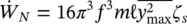
where m is the total mass of the tube per unit length, and  and f are, respectively, the maximum mean‐square vibration amplitude and natural frequency of the tube for the worst mode. The worst mode of a given region is defined as the mode of vibration that has the highest value for the normal work‐rate term,
  , in Eq. (2-52). The length, ℓ, is that of the span where the vibration amplitude is maximum and ζ sis the damping ratio attributed to the supports.
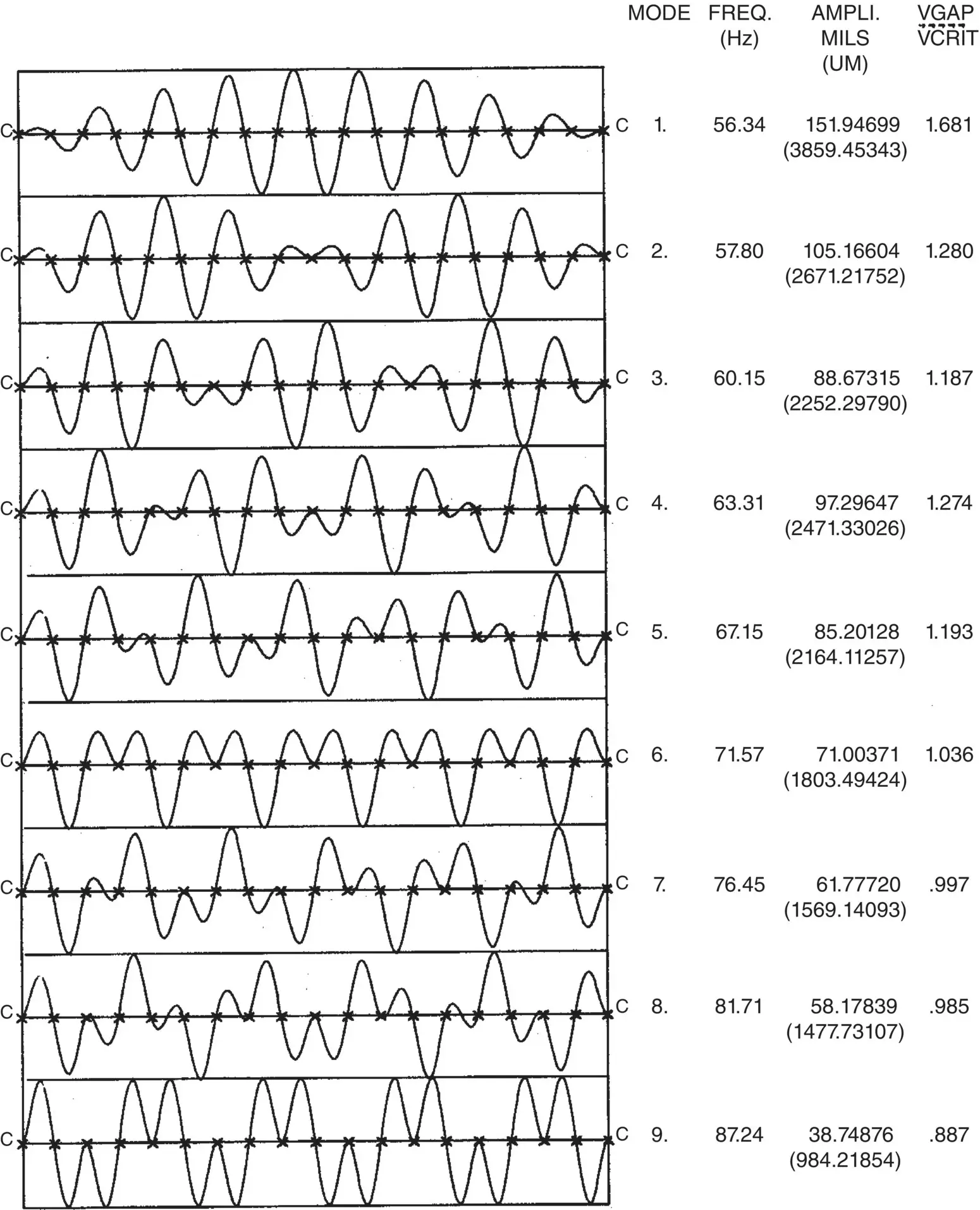
Fig. 2-23 Vibration Mode Shapes and Vibration Analysis Results for a Typical Condenser Tube.
2.6.2 Fretting‐Wear Coefficients
Tube and tube‐support materials should be chosen to minimize fretting‐wear damage. Similar materials such as Inconel 1 ‐600 (I600) tubes and I600 supports must be avoided. Incoloy‐800 (I800), Inconel‐690 (I690) and I600 tubes with 410, 304L, 316L, 321 stainless steel or carbon steel supports are considered acceptable material combinations. A fretting‐wear coefficient, KFW , of 20 x 10 ‐15m 2/N may be used as a first approximation for these tube and support material combinations (Guérout and Fisher, 1999). Other material combinations may be used. However, it would be desirable to obtain reliable fretting‐wear coefficients before choosing the material combination. Fretting‐wear coefficients are discussed in detail in Chapter 13.
The tube supports, whether they be flat bars, lattice bars, broached holes, scalloped bars or circular holes must be deburred to make sure there are no sharp edges between tube and support.
2.6.3 Wear Depth Calculations
To be conservative, it may be assumed that fretting‐wear is taking place continuously for a total time, T , corresponding to the life of the component and equal to half the life of the station, T s. Thus, T = 0.5T sand the total fretting‐wear volume, V , is then calculated from Eq. (2-53):
Читать дальшеИнтервал:
Закладка:
Похожие книги на «Flow-Induced Vibration Handbook for Nuclear and Process Equipment»
Представляем Вашему вниманию похожие книги на «Flow-Induced Vibration Handbook for Nuclear and Process Equipment» списком для выбора. Мы отобрали схожую по названию и смыслу литературу в надежде предоставить читателям больше вариантов отыскать новые, интересные, ещё непрочитанные произведения.


Обсуждение, отзывы о книге «Flow-Induced Vibration Handbook for Nuclear and Process Equipment» и просто собственные мнения читателей. Оставьте ваши комментарии, напишите, что Вы думаете о произведении, его смысле или главных героях. Укажите что конкретно понравилось, а что нет, и почему Вы так считаете.