Doug Lowe - Electronics All-in-One For Dummies
Здесь есть возможность читать онлайн «Doug Lowe - Electronics All-in-One For Dummies» — ознакомительный отрывок электронной книги совершенно бесплатно, а после прочтения отрывка купить полную версию. В некоторых случаях можно слушать аудио, скачать через торрент в формате fb2 и присутствует краткое содержание. Жанр: unrecognised, на английском языке. Описание произведения, (предисловие) а так же отзывы посетителей доступны на портале библиотеки ЛибКат.
- Название:Electronics All-in-One For Dummies
- Автор:
- Жанр:
- Год:неизвестен
- ISBN:нет данных
- Рейтинг книги:5 / 5. Голосов: 1
-
Избранное:Добавить в избранное
- Отзывы:
-
Ваша оценка:
Electronics All-in-One For Dummies: краткое содержание, описание и аннотация
Предлагаем к чтению аннотацию, описание, краткое содержание или предисловие (зависит от того, что написал сам автор книги «Electronics All-in-One For Dummies»). Если вы не нашли необходимую информацию о книге — напишите в комментариях, мы постараемся отыскать её.
Electronics All-in-One For Dummies,
Electronics All-in-One For Dummies
Electronics All-in-One For Dummies — читать онлайн ознакомительный отрывок
Ниже представлен текст книги, разбитый по страницам. Система сохранения места последней прочитанной страницы, позволяет с удобством читать онлайн бесплатно книгу «Electronics All-in-One For Dummies», без необходимости каждый раз заново искать на чём Вы остановились. Поставьте закладку, и сможете в любой момент перейти на страницу, на которой закончили чтение.
Интервал:
Закладка:
Prototyping Your Circuit on a Solderless Breadboard
Before you commit your circuit to a permanent circuit board, you want to make sure it works. The easiest way to do that is to build the circuit on a solderless breadboard. The solderless breadboard lets you quickly assemble the components of your circuit without soldering anything. Instead, you just push the bare wire leads of the various components you need into the holes on the breadboard and then use jumper wires to connect the components together.
The beauty of working with a solderless breadboard is that if the circuit doesn’t work the way you expect it to, you can make changes to the circuit simply by pulling components or jumper wires out and inserting new ones in their place. If you discover that your schematic diagram is missing an important connection, you can add another jumper wire to create the missing connection or, if you want to see how the circuit might work with a different resistor or capacitor, you can pull out the original resistor or capacitor and insert a different one in its place. Figure 6-6 shows a typical solderless breadboard.
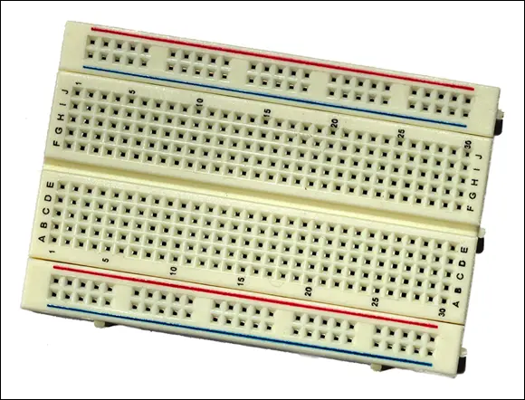
FIGURE 6-6:A typical solderless breadboard.
Understanding how solderless breadboards work
Although many different manufacturers make solderless breadboards, they all work pretty much the same way. The board consists of several hundred little holes called contact holes that are spaced  inch apart. This is a convenient spacing because it also happens to be the standard spacing for the pins that come out of the bottom or sides of most integrated circuits. Thus, you can insert all the pins of even a large integrated circuit directly into a solderless breadboard.
Beneath the plastic surface of the solderless breadboard, the contact holes are connected to one another inside the breadboard. These connections are made according to a specific pattern that’s designed to make it easy to construct even complicated circuits. Figure 6-7 shows how this pattern works.
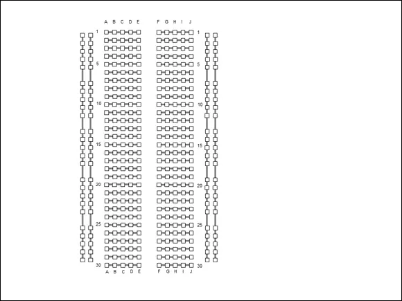
FIGURE 6-7:The contact holes in typical solderless breadboards are internally connected following this pattern.
The holes in the middle portion of a solderless breadboard are connected in groups of five that are called terminal strips. These terminal strips are arranged in two groups, with a long open slot between the two groups, like a little ditch. It is in these holes that you will connect components such as resistors, capacitors, diodes, and integrated circuits.
It’s important to note that the rows of holes are not connected across the ditch. Thus, each row comprises two electrically separate terminal strips: one that connects the holes labeled A through E, the other connecting the holes labeled F through J.
 The breadboard is designed so that integrated circuits can be placed over the top of the ditch, with the pins on either side of the integrated circuit pushed into the holes on either side of the ditch.
The holes on the outside edges of the breadboard are called bus strips. There are two bus strips on either side of the breadboard. For most circuits, you will use the bus strips on one side of the breadboard for the voltage source and use the bus strips on the other side of the board for the ground circuit.
Most solderless breadboards use numbers and letters to designate the individual connection holes in the terminal strips. In Figure 6-7, the rows are labeled with numbers from 1 through 30, and the columns are identified with the letters A through J. Thus, the connection hole in the top-left corner of the terminal strip area is A1, and the hole in the bottom-right corner is J30. The holes in the bus strips are not typically numbered.
Solderless breadboards come in several different sizes. Small breadboards usually have about 30 rows of terminal strips and about 400 holes altogether. But you can get larger breadboards, with 60 or more rows with 800 or more holes.
Laying out your circuit
The most difficult challenge of creating a circuit on a solderless breadboard is the task of translating a schematic diagram into a layout that can be assembled on the breadboard. Only in rare cases will a circuit assembled on a breadboard look like the circuit’s schematic diagram. In most cases, the components are arranged differently and jumper wires are required to connect the components together.
 The key when assembling a circuit on a solderless breadboard is to ensure that every connection represented in the schematic diagram is faithfully re-created on the breadboard. For example, the schematic diagram in Figure 6-4 indicates that pin 1 of the 555 timer IC must be connected to ground. Thus, when you build the circuit on a breadboard, you must ensure that this connection is properly made.
One of the first challenges you face when building a circuit on a breadboard is connecting the pins on an integrated circuit. In a schematic diagram, the pin connections on an integrated circuit are rarely drawn in numerical order. For example, in the schematic diagram shown in Figure 6-4, the pin connections on the 555 timer IC are listed in this order, going counterclockwise from the top left: 7, 6, 2, 1, 3, 8, and 4. (Pin 5 is not used.)
But the pins on an actual 555 timer IC chip are arranged in numerical order starting at the top-left corner of the chip, as shown in Figure 6-8. Notice also that there are pins on the left and right side of the chip but none on the top or bottom. (The dot imprinted on the top of the chip is used to identify pin 1.)
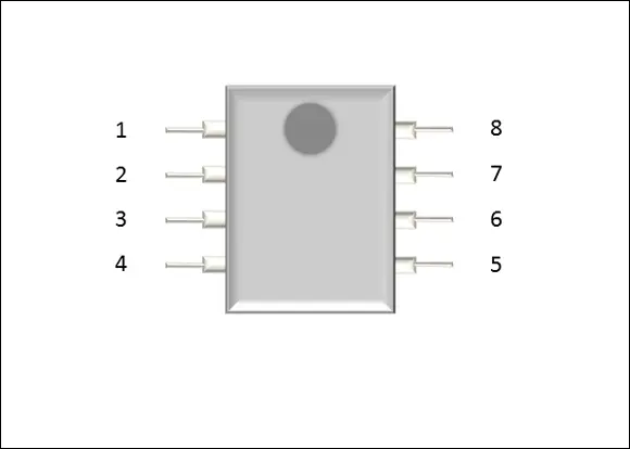
FIGURE 6-8:How the pins are numbered on a 555 timer integrated circuit.
You’ll have to use your wits to re-create a circuit represented by a schematic diagram on a solderless breadboard. Here are some pointers to get you started:
Start by designating the top row of bus strips as the positive power supply and the bottom row as the ground. Connect your battery connector to holes in one end of these bus strips, but don’t yet connect the battery; it’s never a good idea to apply power to your circuit before you’ve finished assembling it.
Next, insert any ICs required for the circuit. Insert them so that they straddle the ditch in the middle of the terminal rows and, if your circuit has more than one IC, orient them all the same. You’ll only confuse yourself if pin 1 is on the bottom-left corner of some of your ICs and on the top-right corner of others.
Each pin of each IC is connected to a terminal strip that has four additional connection holes. Thus, you can connect as many as four additional components or jumper wires to each pin. If your circuit requires more than four component connections to a single pin, use a jumper wire to extend the pin’s terminal strip to an unused row anywhere on the breadboard.
Читать дальшеИнтервал:
Закладка:
Похожие книги на «Electronics All-in-One For Dummies»
Представляем Вашему вниманию похожие книги на «Electronics All-in-One For Dummies» списком для выбора. Мы отобрали схожую по названию и смыслу литературу в надежде предоставить читателям больше вариантов отыскать новые, интересные, ещё непрочитанные произведения.


Обсуждение, отзывы о книге «Electronics All-in-One For Dummies» и просто собственные мнения читателей. Оставьте ваши комментарии, напишите, что Вы думаете о произведении, его смысле или главных героях. Укажите что конкретно понравилось, а что нет, и почему Вы так считаете.