Doug Lowe - Electronics All-in-One For Dummies
Здесь есть возможность читать онлайн «Doug Lowe - Electronics All-in-One For Dummies» — ознакомительный отрывок электронной книги совершенно бесплатно, а после прочтения отрывка купить полную версию. В некоторых случаях можно слушать аудио, скачать через торрент в формате fb2 и присутствует краткое содержание. Жанр: unrecognised, на английском языке. Описание произведения, (предисловие) а так же отзывы посетителей доступны на портале библиотеки ЛибКат.
- Название:Electronics All-in-One For Dummies
- Автор:
- Жанр:
- Год:неизвестен
- ISBN:нет данных
- Рейтинг книги:5 / 5. Голосов: 1
-
Избранное:Добавить в избранное
- Отзывы:
-
Ваша оценка:
Electronics All-in-One For Dummies: краткое содержание, описание и аннотация
Предлагаем к чтению аннотацию, описание, краткое содержание или предисловие (зависит от того, что написал сам автор книги «Electronics All-in-One For Dummies»). Если вы не нашли необходимую информацию о книге — напишите в комментариях, мы постараемся отыскать её.
Electronics All-in-One For Dummies,
Electronics All-in-One For Dummies
Electronics All-in-One For Dummies — читать онлайн ознакомительный отрывок
Ниже представлен текст книги, разбитый по страницам. Система сохранения места последней прочитанной страницы, позволяет с удобством читать онлайн бесплатно книгу «Electronics All-in-One For Dummies», без необходимости каждый раз заново искать на чём Вы остановились. Поставьте закладку, и сможете в любой момент перейти на страницу, на которой закончили чтение.
Интервал:
Закладка:
When you have a general idea for a project, you can flesh out the details. You’ll need to answer questions like these:
What will its user interface be? That is, how will a person work with the device to get it to do what it’s supposed to do?
Will it be a stand-alone device, or will it interact with other devices?
Will it be powered by batteries, or will it plug into a wall outlet to get its power? Or will it be solar powered?
How big will it be? Does it need to be small enough to hold in your hand or fit in your pocket? Or will it sit on a shelf?
The jack-in-the-box Halloween prop is a fairly complicated project — too complicated to use as an illustration this early in the book. So, here’s a simpler project: an electronic decision maker. Have you ever resorted to tossing a coin to make a difficult decision? For this project, you create an electronic version of a coin toss. Instead of flipping a coin into the air to see if it lands heads or tails, you build an electronic device that does the coin toss. That way, you can make decisions even when you’re penniless.
The specifications for the coin-toss project are as follows:
The device will have two LED indicators to indicate heads and tails.
It will also have two small metal contacts, which the user can touch with their finger. When the user touches both of the posts, the LEDs start flashing, alternating back and forth, much like a coin flips end over end when you toss it into the air.
When the user removes his finger from the two metal contacts, one of the two lights will stay lit, indicating whether the result of the coin toss is heads or tails. Which light stays lit will be essentially random.
To conserve battery life, the device will have an on/off push button. The user must depress the push button to make the device work; when the button is released, the device is turned off.
The device will be battery powered and contained in an enclosure small enough to hold in your hand.
 As you flesh out the details for your project, you may want to start drawing diagrams to show how it will look. Figure 6-2 shows a hand-drawn sketch I created for the electronic coin tosser.
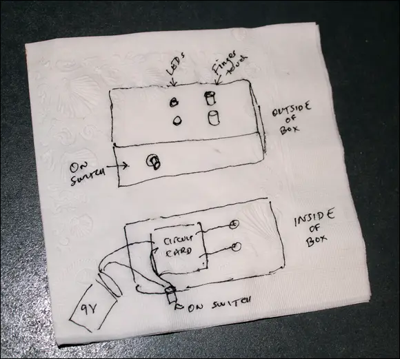
FIGURE 6-2:A hand-drawn sketch for an electronic coin tosser.
Designing Your Circuit
After you have an idea for a project, the next step is to design a circuit that meets the project’s needs. At first, you’ll find it very difficult to design your own circuits, so you’ll turn to books like this one or to the Internet to find other people’s circuit designs. With a bit of Google searching, you can probably find a schematic diagram that’s very close to what your project needs.
In many cases, you won’t be able to find exactly the circuit you’re looking for. You may find a circuit that’s close, but you may need to make minor modifications to make the circuit fit your project’s needs. At first, making modifications to a circuit may seem beyond your abilities. But as you gain experience, you’ll find yourself tweaking circuits all the time to fit specific applications.
One helpful strategy for designing circuits is to break complex requirements down into simpler parts. For example, consider the pop-up jack-in-the-box Halloween prop I mention earlier. The complete circuit for this project required several different elements, including these:
A circuit to detect when someone has entered the room to trigger the prop’s action
A circuit to open and close the jack-in-the-box
A circuit to time how long the jack-in-the-box should stay open
A circuit that plays a screaming sound
A circuit that provides a 30-second delay before the prop is activated again
The coin-toss project is much simpler than the jack-in-the-box project. In fact, a quick Google search will turn up several possible circuits that do almost exactly what the coin-toss project requires. For example, Figure 6-3 shows the schematic diagram for a typical coin-toss circuit you might find on the Internet. This circuit diagram uses a 555 Timer integrated circuit, four resistors, two LEDs, one capacitor, a switch, and a 9 V power supply (most likely a 9 V battery).
The schematic diagram shown in Figure 6-3 differs from our project’s needs in just two ways. First, it doesn’t have an on/off switch. And second, it uses a push button instead of the user’s fingers to start and stop the LEDs from flashing.
Figure 6-4 shows the schematic after I made those modifications. As you can see, I added a push-button switch that must be pressed to provide the +9 V voltage needed to run the circuit, and I replaced the push button that was in the original schematic with two open terminals. When the user touches these two terminals, the resistance of their finger completes the circuit.
 Please don’t worry at all if you don’t understand how the circuit depicted in Figure 6-4 works. I wouldn’t expect you to at this point in the book! Understanding how a circuit works and building that circuit are two entirely different things; you can (and probably will) build plenty of circuits whose operation you don’t understand. The only thing you should focus on at this point is how the schematic diagram indicates the various connections between the parts in the circuit. You learn the details of how this circuit works in Book 3, Chapter 2.
One final step you might want to consider when designing a circuit is to create a final version of the schematic diagram that indicates what components will be mounted on your final circuit board and what components won’t be on the circuit board. This diagram will come in handy later when you’re ready to create the circuit board that will become the permanent home of your circuit.
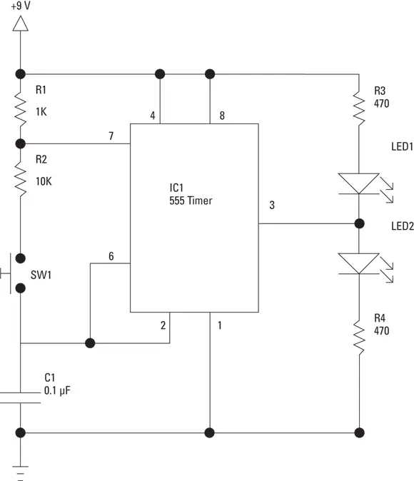
FIGURE 6-3:A schematic diagram for a simple coin-toss circuit.
For example, Figure 6-5 shows a version of the coin-toss circuit that uses a dashed line to delineate the items that won’t be mounted on the circuit board: the battery power supply (that is, the +9 V voltage source and the ground), the push-button power switch, the two metal finger contacts, and the two LEDs. Instead, they’ll be mounted separately within the project box. Thus, the circuit board will need to hold only six components: the 555 timer integrated circuit, the four resistors, and the capacitor.
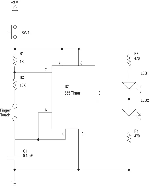
FIGURE 6-4:The schematic diagram for the coin-toss circuit after it has been modified a bit for our project.
After you’ve completed your circuit design, you’ll want to compile a list of all the parts you’ll need to build the circuit. Then, you can rummage through your parts bin to figure out what parts you already have at your disposal and what parts you’ll need to purchase. Here’s a list of the components you’ll need to build the coin-toss circuit:
| Part ID | Description |
|---|---|
| R1 | 1 kΩ, ¼ W resistor |
| R2 | 10 kΩ, ¼ W resistor |
| R3 | 470 Ω, ¼ W resistor |
| R4 | 470 Ω, ¼ W resistor |
| C1 | 0.1 μF capacitor |
| LED1 | 5 mm red LED |
| LED2 | 5 mm green LED |
| IC1 | 555 timer IC |
| SW1 | Momentary-contact, normally open push button |
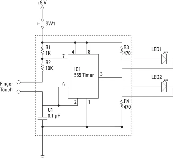
FIGURE 6-5:A schematic diagram that indicates which components are on the main circuit board and which aren’t.
Читать дальшеИнтервал:
Закладка:
Похожие книги на «Electronics All-in-One For Dummies»
Представляем Вашему вниманию похожие книги на «Electronics All-in-One For Dummies» списком для выбора. Мы отобрали схожую по названию и смыслу литературу в надежде предоставить читателям больше вариантов отыскать новые, интересные, ещё непрочитанные произведения.


Обсуждение, отзывы о книге «Electronics All-in-One For Dummies» и просто собственные мнения читателей. Оставьте ваши комментарии, напишите, что Вы думаете о произведении, его смысле или главных героях. Укажите что конкретно понравилось, а что нет, и почему Вы так считаете.