Doug Lowe - Electronics All-in-One For Dummies
Здесь есть возможность читать онлайн «Doug Lowe - Electronics All-in-One For Dummies» — ознакомительный отрывок электронной книги совершенно бесплатно, а после прочтения отрывка купить полную версию. В некоторых случаях можно слушать аудио, скачать через торрент в формате fb2 и присутствует краткое содержание. Жанр: unrecognised, на английском языке. Описание произведения, (предисловие) а так же отзывы посетителей доступны на портале библиотеки ЛибКат.
- Название:Electronics All-in-One For Dummies
- Автор:
- Жанр:
- Год:неизвестен
- ISBN:нет данных
- Рейтинг книги:5 / 5. Голосов: 1
-
Избранное:Добавить в избранное
- Отзывы:
-
Ваша оценка:
Electronics All-in-One For Dummies: краткое содержание, описание и аннотация
Предлагаем к чтению аннотацию, описание, краткое содержание или предисловие (зависит от того, что написал сам автор книги «Electronics All-in-One For Dummies»). Если вы не нашли необходимую информацию о книге — напишите в комментариях, мы постараемся отыскать её.
Electronics All-in-One For Dummies,
Electronics All-in-One For Dummies
Electronics All-in-One For Dummies — читать онлайн ознакомительный отрывок
Ниже представлен текст книги, разбитый по страницам. Система сохранения места последней прочитанной страницы, позволяет с удобством читать онлайн бесплатно книгу «Electronics All-in-One For Dummies», без необходимости каждый раз заново искать на чём Вы остановились. Поставьте закладку, и сможете в любой момент перейти на страницу, на которой закончили чтение.
Интервал:
Закладка:
4 Connect a jumper wire from pin 2 of the IC to the other metal contact.Insert one end of a short jumper wire into hole B15 and the other end into hole B9.
5 Insert the two jumper wires that simulate the metal contacts.Pick out a couple of jumper wires long enough to reach from row 9 and dangle an inch or so over the edge of the breadboard. Insert one end of these wires into holes E9 and F9 and leave the other ends free. Separate the ends of the two jumper wires to make sure that they’re not touching; they should be about ½ inch apart.Figure 6-11 shows what the breadboard looks like after these steps.
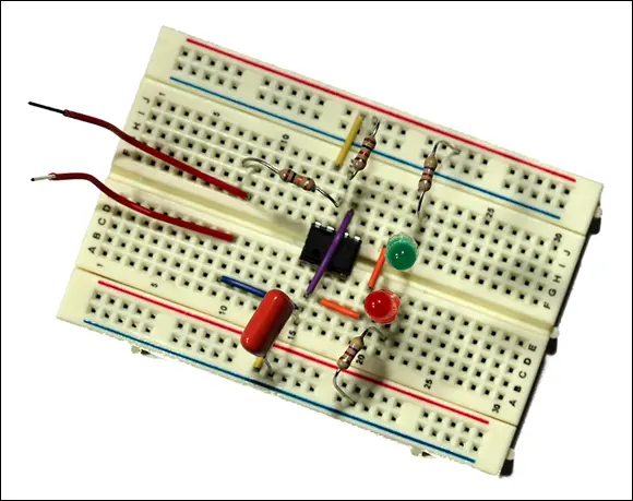
FIGURE 6-11:The breadboard after the finger contact jumpers have been connected.
The remaining two steps complete the circuit by connecting the power supply.
1 Connect the battery snap connector.The leads on the battery snap connector use stranded rather than solid wire, so you’ll need to prepare them a bit before you insert them into the breadboard. Use your wire strippers to strip off about ½ inch of insulation from the end of both leads.Use your fingers to twist the leads as tightly as you can, so that no individual strands are protruding from the very tip of the wire.Insert the red lead into the last hole of the topmost row and insert the black lead into the last hole of the bottommost row.
2 Connect the 9 V battery to the snap connector.The red LED should immediately light up. (If not, see the troubleshooting tips in the next section.)
You can now test the circuit by touching both of the two free jumper wires. Pinch them both between your thumb and index finger, but don’t let the wires actually touch each other. The resistance in your skin will conduct enough current to complete the circuit, and the LEDs will start alternately flashing red, green, red, green, and so on. They will continue to flash until you let go of the jumper wires. Then, one or the other will stay lit. When you touch the wires again, the flashing will resume.
Figure 6-12 shows the completed circuit in operation.
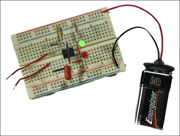
FIGURE 6-12:The prototype of the coin tosser in operation.
Notice that if you squeeze the wires tightly, the rate at which the LEDs flash increases. If you squeeze tight enough, the LEDs will flash so fast that both will appear to be solid on. The LEDs are still flashing alternately, but they’re flashing faster than your eye’s ability to discern the difference, so they appear to be on constantly.
What if it doesn’t work?
If your circuit doesn’t work, there are a number of troubleshooting steps you can take to find out why and correct the problem. Here are some helpful troubleshooting tips:
Examine all the component leads to make sure none of them are touching each other. If any of the leads are touching, gently adjust them so that they’re not touching.
Make sure that the circuit is getting power. Use your multimeter to test the battery voltage (see Chapter 8of this minibook for information on how to do that), and verify that the leads from the battery snap connector are inserted properly into the solderless breadboard.
Carefully double-check your wiring to make sure that every jumper and every component has been inserted in the correct spot.
Verify the orientation of the 555 timer IC, making sure that pin 1 is in hole E14 and pin 8 is in hole F14.
Verify that the LEDs are inserted in the correct direction. For the red LED, the short lead (the cathode) goes in D21, and the long lead (the anode) goes in D19. For the green LED, the short lead (the cathode) goes in G19, and the long lead (the anode) goes in G21.
Constructing Your Circuit on a Printed Circuit Board (PCB)
When you’re satisfied with the operation of your circuit, the next step is to build a permanent version of the circuit. Although there are several ways to do that, the most common is to construct the circuit on a printed circuit board, also called a PCB. In the following sections, you learn how printed circuit boards work and how to assemble the coin-toss circuit on a PCB.
 Note that assembling a circuit on a PCB requires that you know how to solder. To learn that all-important skill, see Chapter 7of this minibook.
Understanding how printed circuit boards work
A printed circuit board is made from a layer of insulating material such as plastic or some similar material. Copper circuit paths are bonded to one side of the board. The circuit paths consist of traces, which are like the wires that connect components, and pads, which are small circles of copper that the component leads can be soldered to. Figure 6-13 shows a typical printed circuit board.
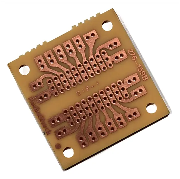
FIGURE 6-13:A printed circuit board.
There are two basic styles of printed circuit boards available:
Through-hole: A PCB in which the copper circuits are on one side of the board and the components are installed on the opposite side. In a through-hole PCB, small holes (usually inch in diameter) are drilled through the board at the center of the copper pads. Components are mounted to the blank side of the board by passing their leads through the holes and soldering the leads to the copper pads on the other side of the board. When the solder joint is completed, any excess wire lead is trimmed away.
Surface-mount: A PCB in which the components are installed on the same side of the board as the copper circuits. No holes are drilled.
Surface-mount PCBs are easier for large-scale automated circuit assembly. However, they’re much more difficult to work with as a hobbyist because the components tend to be smaller and the leads are closer together. Thus, all the PCBs used in this book are of the through-hole variety.
Using a preprinted PCB
The easiest way to work with printed circuit boards is to purchase a preprinted board from an electronics parts supplier. You’ll find a wide variety of preprinted PCBs at online distributors such as Hobby Engineering ( www.hobbyengineering.com ), Jameco Electronics ( www.jameco.com ), or All Electronics ( www.allelectronics.com ).
As you can see, preprinted PCBs come in a wide variety of shapes and sizes. The most useful, from a hobbyist’s point of view, are the ones that mimic the terminal-strip and bus-strip layout of a solderless breadboard. For example, Figure 6-14 shows a PCB that has 550 holes laid out in a standard breadboard arrangement. With a preprinted PCB that has a breadboard layout, you can transfer your breadboard prototype circuit to the PCB without having to come up with an entirely new layout.
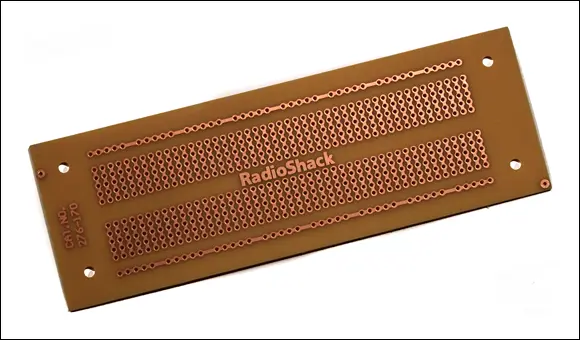
FIGURE 6-14:A preprinted PCB that uses a standard breadboard layout.
Some preprinted circuit boards have layouts that are similar to standard breadboard layouts, but not identical. So check carefully before you build; you may have to make minor adjustments to your circuit layout to accommodate the PCB you’re using.
Читать дальшеИнтервал:
Закладка:
Похожие книги на «Electronics All-in-One For Dummies»
Представляем Вашему вниманию похожие книги на «Electronics All-in-One For Dummies» списком для выбора. Мы отобрали схожую по названию и смыслу литературу в надежде предоставить читателям больше вариантов отыскать новые, интересные, ещё непрочитанные произведения.


Обсуждение, отзывы о книге «Electronics All-in-One For Dummies» и просто собственные мнения читателей. Оставьте ваши комментарии, напишите, что Вы думаете о произведении, его смысле или главных героях. Укажите что конкретно понравилось, а что нет, и почему Вы так считаете.