Doug Lowe - Electronics All-in-One For Dummies
Здесь есть возможность читать онлайн «Doug Lowe - Electronics All-in-One For Dummies» — ознакомительный отрывок электронной книги совершенно бесплатно, а после прочтения отрывка купить полную версию. В некоторых случаях можно слушать аудио, скачать через торрент в формате fb2 и присутствует краткое содержание. Жанр: unrecognised, на английском языке. Описание произведения, (предисловие) а так же отзывы посетителей доступны на портале библиотеки ЛибКат.
- Название:Electronics All-in-One For Dummies
- Автор:
- Жанр:
- Год:неизвестен
- ISBN:нет данных
- Рейтинг книги:5 / 5. Голосов: 1
-
Избранное:Добавить в избранное
- Отзывы:
-
Ваша оценка:
Electronics All-in-One For Dummies: краткое содержание, описание и аннотация
Предлагаем к чтению аннотацию, описание, краткое содержание или предисловие (зависит от того, что написал сам автор книги «Electronics All-in-One For Dummies»). Если вы не нашли необходимую информацию о книге — напишите в комментариях, мы постараемся отыскать её.
Electronics All-in-One For Dummies,
Electronics All-in-One For Dummies
Electronics All-in-One For Dummies — читать онлайн ознакомительный отрывок
Ниже представлен текст книги, разбитый по страницам. Система сохранения места последней прочитанной страницы, позволяет с удобством читать онлайн бесплатно книгу «Electronics All-in-One For Dummies», без необходимости каждый раз заново искать на чём Вы остановились. Поставьте закладку, и сможете в любой момент перейти на страницу, на которой закончили чтение.
Интервал:
Закладка:
 If necessary, you can cut a larger PCB to a smaller size. One way to cut a PCB is to score it on both sides with a heavy-duty utility knife, and then snap it at the score. Another way is to cut it with a rotary tool such as a Dremel.
CREATING A CUSTOM PCB
As you get more advanced in your electronics skills, you may find that you want to create your own custom-printed circuit boards rather than force your circuit designs to fit the limited variety of preprinted circuit boards that are available. Although it isn’t a trivial or inexpensive process, it’s possible to make your own printed circuit boards customized for your circuit.
Here are the basic steps for creating your own printed circuit boards:
1 Purchase a blank PCB. The entire surface of one side of this board will be completely coated with copper.
2 Create a mask on the copper surface that indicates the circuit layout.There are several ways to do this. For simple circuits, you can simply hand-draw the circuit onto the copper using a special pen designed for this purpose. For more complicated circuits, you can purchase special stickers that are shaped like pads and common traces and place the stickers directly on the copper. Or you can design the circuit on your computer using any graphics drawing software, print the design on special paper, and transfer the design to the copper using a hot iron.
3 Etch the board by dipping it into a special chemical that eats away all the copper that isn’t covered by your mask.This is a nasty process that needs to be done outside in a well-ventilated area while wearing gloves, a face mask, and goggles. When the etching is finished, all the copper that wasn’t covered by the mask will be gone.
4 Wash the board to get all that nasty copper etching solution off.
5 Scrub away the mask to reveal the beautiful copper circuit pattern left behind.
6 Drill holes in the center of each pad, and then assemble your circuit.
Note that there are several companies on the Internet that will make small printed circuit boards for you. It isn’t cheap, but the price per board comes down dramatically if you have them make more than just one. For example, PCBWay ( www.pcbway.com ) will make 4-inch-square circuit boards for about $3 per board if you order ten.
Building the coin-toss circuit on a PCB
This section presents a complete procedure for building the coin-toss circuit on a small preprinted PCB. When you get all your materials together, you should be able to complete this project in about an hour.
All the parts required to build this prototype circuit can be purchased from your local RadioShack. Or, you can order them online from any electronic parts supplier. For your convenience, here is a complete list of the parts you’ll need to build this prototype circuit, along with the RadioShack catalog part numbers:
| Quantity | Description |
|---|---|
| 1 | General-purpose, dual-printed circuit board |
| 1 | LM555 timer IC |
| 1 | 1 kΩ, ¼ W resistor (5 per package) |
| 1 | 10 kΩ, ¼ W resistor (5 per package) |
| 2 | 470 Ω, ¼ W resistor (5 per package) |
| 1 | 0.1 μF polyester film capacitor |
| 1 | Red LED 5 mm |
| 1 | Green LED 5 mm |
| 1 | Normally open, momentary-contact push button |
| 1 | 9 V battery snap connector |
| 1 | 9 V battery |
You will also need about a foot each of 22-gauge solid insulated wire and 22-gauge stranded insulated wire. The color doesn’t matter.
Note: This list is similar to the list I give earlier in this chapter for building the coin-toss circuit on a solderless breadboard. If you have the parts from that project, you can reuse them here.
Figure 6-15 shows the layout of the preprinted circuit board. Before we start building the circuit, study the layout of this board for a moment to familiarize yourself with it. As you can see, this board doesn’t contain bus strips like those found on a breadboard. However, the overall layout of the board is similar to the layout of the terminal strips on a breadboard. The center portion of the board contains a total of 20 terminal strips, 10 on each side of the ditch. Each strip has three holes but is also connected to a second strip of two holes along the edge of the board. Thus, each strip effectively has five holes.
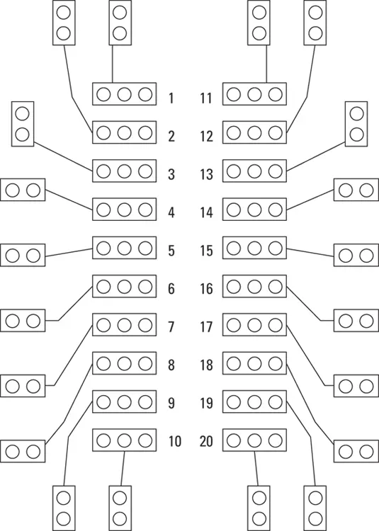
FIGURE 6-15:The layout for the PCB used in the coin-toss circuit.
The strips aren’t numbered on the board, but I’ve numbered them in Figure 6-15. I use the numbers 1 through 10 to number the strips on the left side of the board and the numbers 11 through 20 to number the strips on the right. In the instructions that follow, I use these numbers to indicate which holes to attach components or jumper leads to. Note: To keep things simple, I just specify the terminal strip number and leave it up to you to decide which of the five holes in the strip to use.
 The numbers used in the PCB layout are relative to the bottom of the board — that is, the surface of the board with the copper traces and pads. Thus, the numbers 1 through 10 are on the left and the numbers 11 through 20 are on the right. When you flip the board over to insert components from the top of the board, you’ll have to mentally reverse the numbers: 1 through 10 is on the right and 11 through 20 is on the left.
When installing components onto the PCB, use an alligator clip as a temporary clamp to hold the components flush against the board. This will enable you to turn the board upside down so that you can solder the leads to the pads. If you don’t clamp the component to the board, the component will fall out when you turn the board upside down, or you’ll be tempted to hold the component in place with one finger while you solder the leads. Bad idea: Resistors get really hot when you solder them.
Here are the steps for building the coin-toss circuit on a preprinted PCB.
1 Break the PCB in half.The preprinted circuit board comes with two identical sections. You need just one of those sections for this project, so you can break the board in half and save the other half for another project. (To break the board, just grab an end in each hand and snap it in two.)
2 Insert the 555 timer IC.Remember that the dot or notch on the 555 IC marks pin 1. Install the chip so that pin 1 is in strip 4 and pin 8 is in strip 14. Then solder the chip carefully into place. (See Chapter 7of this minibook for tips on soldering.)
3 Install the jumper wires.This circuit needs a total of nine jumper wires. Cut the jumper wires from the 22-gauge solid wire and carefully strip the insulation from each end. Use needle-nosed pliers to bend the bare end of each jumper wire down, insert both ends into the appropriate holes, solder the leads to the pads, and then use your wire cutters to snip the excess of the end of each lead.The following table provides the PCB strip locations for each jumper wire. Use your own judgment to determine which hole in the indicated strip to place the jumper wire in. Whenever possible, use the shortest possible path for each jumper wire.Jumper NumberFrom stripTo strip191021920351644105719626715821291419
Читать дальшеИнтервал:
Закладка:
Похожие книги на «Electronics All-in-One For Dummies»
Представляем Вашему вниманию похожие книги на «Electronics All-in-One For Dummies» списком для выбора. Мы отобрали схожую по названию и смыслу литературу в надежде предоставить читателям больше вариантов отыскать новые, интересные, ещё непрочитанные произведения.


Обсуждение, отзывы о книге «Electronics All-in-One For Dummies» и просто собственные мнения читателей. Оставьте ваши комментарии, напишите, что Вы думаете о произведении, его смысле или главных героях. Укажите что конкретно понравилось, а что нет, и почему Вы так считаете.