Doug Lowe - Electronics All-in-One For Dummies
Здесь есть возможность читать онлайн «Doug Lowe - Electronics All-in-One For Dummies» — ознакомительный отрывок электронной книги совершенно бесплатно, а после прочтения отрывка купить полную версию. В некоторых случаях можно слушать аудио, скачать через торрент в формате fb2 и присутствует краткое содержание. Жанр: unrecognised, на английском языке. Описание произведения, (предисловие) а так же отзывы посетителей доступны на портале библиотеки ЛибКат.
- Название:Electronics All-in-One For Dummies
- Автор:
- Жанр:
- Год:неизвестен
- ISBN:нет данных
- Рейтинг книги:5 / 5. Голосов: 1
-
Избранное:Добавить в избранное
- Отзывы:
-
Ваша оценка:
Electronics All-in-One For Dummies: краткое содержание, описание и аннотация
Предлагаем к чтению аннотацию, описание, краткое содержание или предисловие (зависит от того, что написал сам автор книги «Electronics All-in-One For Dummies»). Если вы не нашли необходимую информацию о книге — напишите в комментариях, мы постараемся отыскать её.
Electronics All-in-One For Dummies,
Electronics All-in-One For Dummies
Electronics All-in-One For Dummies — читать онлайн ознакомительный отрывок
Ниже представлен текст книги, разбитый по страницам. Система сохранения места последней прочитанной страницы, позволяет с удобством читать онлайн бесплатно книгу «Electronics All-in-One For Dummies», без необходимости каждый раз заново искать на чём Вы остановились. Поставьте закладку, и сможете в любой момент перейти на страницу, на которой закончили чтение.
Интервал:
Закладка:
 In reality, conventional current flow is the opposite of the actual flow of electrons through the circuit. The negative side of the battery has an excess of negatively charged particles (extra electrons) whereas the positive side has an excess of positively charged particles (missing electrons). Thus, the electric charge flows through the conductor from the negative side of the battery, through the lamp, and back to the positive side. (For more about the difference between real current flow and conventional current flow, see Chapter 2of this minibook.)
As it passes through the lamp, the resistance of the lamp’s filament causes the current to heat the filament, which in turn causes the filament to emit visible light.
Laying Out a Circuit
One of the most important things to realize about a schematic diagram is that the arrangement of components in the diagram doesn’t necessarily correspond to the physical arrangement of parts in the circuit when you actually build the circuit.
For example, the circuit shown in Figure 5-1 shows the battery on the left side of the circuit and the lamp on the right. It also shows the battery oriented so that the positive terminal is at the top and the negative terminal is at the bottom. However, that doesn’t mean the circuit would actually have to be built that way. If you want, you could put the lamp on the left and the battery on the right, or you could put the battery at the top and the lamp on the bottom.
The physical arrangement of the circuit doesn’t matter as long as the component connections remain the same as shown in the schematic. Thus, in this example, no matter how you physically arrange the components, you must connect the positive terminal of the battery to one lead of the lamp and the negative terminal to the other lead.
Because there are only two components and two conductors in the circuit shown in Figure 5-1, it would be pretty hard to mess up the connections. However, in a more complicated circuit with perhaps dozens of components and dozens of connections, laying out the circuit and making sure that all the connections exactly match the connections indicated in the schematic can be a challenge. Each connection must be checked carefully to make sure it’s correct.
To Connect or Not to Connect
One of the goals when laying out a schematic circuit diagram is to keep the diagram as simple as possible. However, the lines in all but the simplest of schematic diagrams will at some places need to cross over each other. When they do, it’s vital that you can tell whether the lines that cross represent actual connections (also called junctions ) between the conductors or whether the lines cross over each other but don’t actually connect.
Unfortunately, there isn’t one clear and universally used standard that dictates how to indicate whether crossed lines represent a junction. Figure 5-2 shows some of the ways for showing crossed wires with or without junctions.
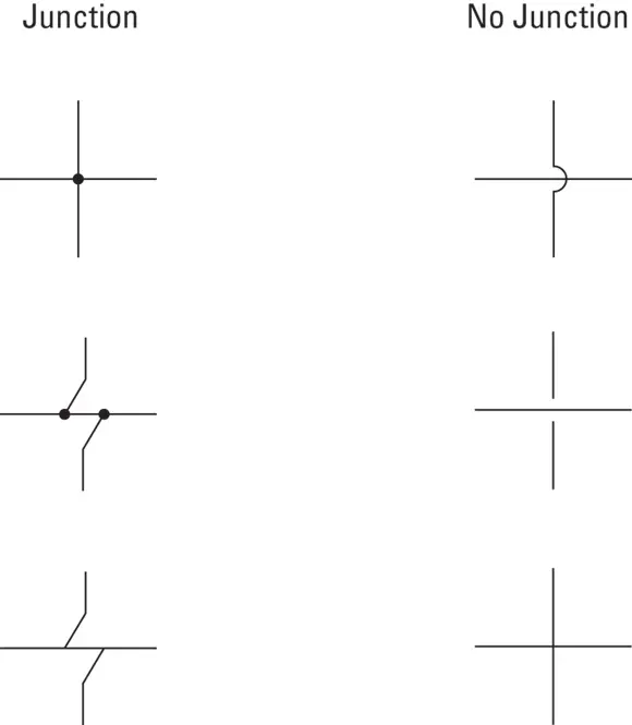
FIGURE 5-2:Wires that cross may or may not actually be connected.
The three examples on the left side of Figure 5-2 show how junctions are indicated. The example at the top left shows the most common way to indicate a junction: by placing a conspicuous dot at the point where the wires cross. Any time you see a dot where two lines intersect, you know that the two lines form a junction.
In the two junction styles shown in the middle-left and bottom-left examples in Figure 5-2, the vertical lines are angled to avoid coming together at the same spot on the horizontal line. With or without the dot, junctions are clearly indicated in both of these examples.
The three examples on the right side of Figure 5-2 show how lines that cross but don’t connect to form junctions are most commonly shown. In the top two examples, one line “hops” over the other, and one of the lines is broken at the spot where it crosses the other.
The example in the bottom-right corner of Figure 5-2 is a bit ambiguous. Here, the lines cross each other. However, there’s no hop or break to indicate that no junction is present, nor is there a dot to indicate that a junction should be present. So is there a junction here or not? The answer is, in most cases, no. You can usually assume that a junction is not present when lines cross but there’s no dot. However, you should examine the rest of the diagram to make sure. If you find other places in the diagram where nonjunctions are indicated by a hop or a break, the crossed lines without the hop or break may indeed indicate a junction.
 To avoid ambiguity altogether, the schematic diagrams in this book always use a dot to indicate a junction and a hop to indicate a nonjunction. You’ll never see lines simply cross without a hop or a dot.
Looking at Commonly Used Symbols
The circuit shown in Figure 5-1 has just two components: a battery and a lamp. Most electronic circuits will have additional components. There are hundreds of different types of electronic components, and each has its own unique schematic diagram symbol. Fortunately, you need to know only a few basic symbols to get started. These symbols are summarized in Table 5-1. (Note that when used in an actual circuit diagram, the symbols are often rotated.)
Figure 5-3 shows a schematic diagram that includes several of these components. Don’t worry — you don’t need to understand this diagram right now. I just want you to get an idea of what real-world schematic diagrams look like and how to read them.
TABLE 5-1Common Symbols for Schematic Diagrams
| Symbol | Description |
|---|---|
 |
Battery |
 |
Capacitor |
 |
Diode |
 |
Ground |
 |
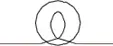
Inductor (coil) |
 |
Lamp |
 |
Light-emitting diode |
 |
Resistor |
 |
Source voltage connection |
 |
Speaker |
 |
Switch |
 |
Transformer |
 |
Transistor (NPN) |
 |
Transistor (PNP) |
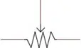 |
Variable resistor (potentiometer) |
As you can see, the circuit shown in Figure 5-3 contains six components. Working from left to right, they are:
Читать дальшеИнтервал:
Закладка:
Похожие книги на «Electronics All-in-One For Dummies»
Представляем Вашему вниманию похожие книги на «Electronics All-in-One For Dummies» списком для выбора. Мы отобрали схожую по названию и смыслу литературу в надежде предоставить читателям больше вариантов отыскать новые, интересные, ещё непрочитанные произведения.


Обсуждение, отзывы о книге «Electronics All-in-One For Dummies» и просто собственные мнения читателей. Оставьте ваши комментарии, напишите, что Вы думаете о произведении, его смысле или главных героях. Укажите что конкретно понравилось, а что нет, и почему Вы так считаете.