Handbook of Aggregation-Induced Emission, Volume 2
Здесь есть возможность читать онлайн «Handbook of Aggregation-Induced Emission, Volume 2» — ознакомительный отрывок электронной книги совершенно бесплатно, а после прочтения отрывка купить полную версию. В некоторых случаях можно слушать аудио, скачать через торрент в формате fb2 и присутствует краткое содержание. Жанр: unrecognised, на английском языке. Описание произведения, (предисловие) а так же отзывы посетителей доступны на портале библиотеки ЛибКат.

- Название:Handbook of Aggregation-Induced Emission, Volume 2
- Автор:
- Жанр:
- Год:неизвестен
- ISBN:нет данных
- Рейтинг книги:4 / 5. Голосов: 1
-
Избранное:Добавить в избранное
- Отзывы:
-
Ваша оценка:
Handbook of Aggregation-Induced Emission, Volume 2: краткое содержание, описание и аннотация
Предлагаем к чтению аннотацию, описание, краткое содержание или предисловие (зависит от того, что написал сам автор книги «Handbook of Aggregation-Induced Emission, Volume 2»). Если вы не нашли необходимую информацию о книге — напишите в комментариях, мы постараемся отыскать её.
, the editors address the design and synthesis of typical AIEgens that have made significant contributions to aggregation-induced emission research. Recent advances in the development of aggregation-induced emission systems are discussed and the book covers novel aggregation-induced emission systems in small molecule organogels, polymersomes, metal-organic coordination complexes and metal nanoclusters. Readers will also discover:
A thorough introduction to the synthesis and applications of tetraphenylpyrazine-based AIEgens, AIEgens based on 9,10-distyrylanthracene , and the Salicylaldehyde Schiff base Practical discussions of aggregation-induced emission from the sixth main group and fluorescence detection of dynamic aggregation processes using AIEgens Coverage of cyclic triimidazole derivatives and the synthesis of multi-phenyl-substituted pyrrole based materials and their applications Perfect for academic researchers working on aggregation-induced emission, this set of volumes is also ideal for professionals and students in the fields of photophysics, photochemistry, materials science, optoelectronic materials, synthetic organic chemistry, macromolecular chemistry, polymer science, and biological sciences.
Handbook of Aggregation-Induced Emission, Volume 2 — читать онлайн ознакомительный отрывок
Ниже представлен текст книги, разбитый по страницам. Система сохранения места последней прочитанной страницы, позволяет с удобством читать онлайн бесплатно книгу «Handbook of Aggregation-Induced Emission, Volume 2», без необходимости каждый раз заново искать на чём Вы остановились. Поставьте закладку, и сможете в любой момент перейти на страницу, на которой закончили чтение.
Интервал:
Закладка:
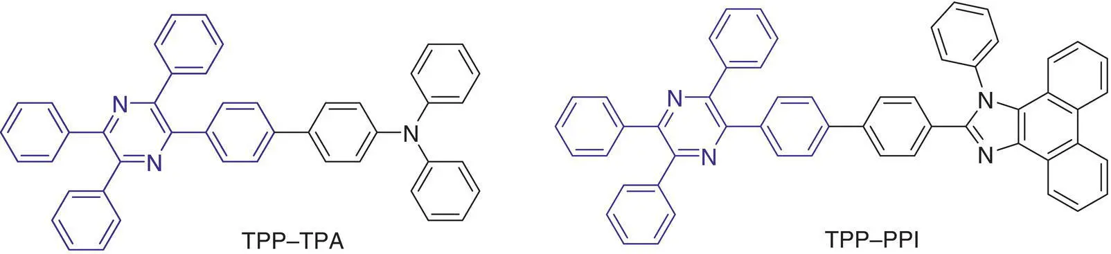
Chart 1.2 Molecular structures of TPP–TPA and TPP–PPI.
Table 1.1 EL performance of devices.
| λ EL(nm) | V on a(V) | L max b(cd/m 2) | η C b(lm/W) | η P b(lm/W) | EQE b(%) | CIE ( x , y ) b | |
|---|---|---|---|---|---|---|---|
| TPP–TPA (I) | 482 | 3.7 | 17 459 | 5.49 | 3.18 | 2.88 | — |
| TPP–TPA (II) | 472 | 2.8 | 19 170 | 6.57 | 6.55 | 4.08 | 0.15, 0.21 |
| TPP–PPI | 474 c | 2.9 | 16 460 | 8.34 | 8.18 | 4.85 | 0.16, 0.23 c |
a V on= turn‐on voltage at 1 cd/m 2.
bThe maximum luminescence ( L max), current efficiency ( η C), power efficiency ( η P), and external quantum efficiency at the maximum values for the devices.
cData recorded at a luminescence of 1000 cd/m 2.
It was later reported that TPP derivatives with a D–A structure possess a planarized intramolecular charge transfer (PLICT) effect in the excited state in the polar media. For example, the Φ Fof TPP–TPA in toluene, ethyl acetate, dichloromethane, and DMF changes from 22.7, 50.9, 80.7 to 80.9% as the polarity of the solvent increases. It is due to the formation of planarization conformation or quinone conformation with a good conjugation in the excited state to increase the probability of transition. In that work, another TPP–TPA‐based blue OLED (configuration: ITO/HATCN (5 nm)/TAPC (40 nm)/TCTA (5 nm)/TPP–TPA (20 nm)/Bepp2 (45 nm)/Liq (2 nm)/Al) is fabricated with HATCN (2,3,6,7,10,11‐hexacyano‐1,4,5,8,9,12‐hexaazatriphe‐nylene), TAPC (1,1‐bis(4‐di‐ p ‐tolylaminophenyl)cyclohexane), TCTA (4,4′,4′′‐tri‐9‐carbazolytriphenylamine), and Bepp2 (bis(2‐(2‐hydroxyphenyl)‐pyridine)beryllium) functioned as hole‐injecting layer, hole‐transporting layer, hole‐transporting and electron‐blocking layer, and electron‐transporting and hole‐blocking layer, respectively. However, a very good device performance with V on, L max, and EQE of 2.8 V, 19 170 cd/m 2, and 4.08%, respectively, is obtained ( Table 1.1, Device II) [51].
The PLICT effect also takes places in phenanthroimidazole derivative‐modified TPP (TPP–PPI), though the phenanthroimidazole‐based group is not so electron‐donating ( Chart 1.2). TPP‐PPI shows the AIE effect in THF/water mixtures and emits at 470 nm in the film with Φ Fof 28.1%. While fabricating it into the device with a configuration of ITO/HATCN (5 nm)/NPB (40 nm)/TcTa (5 nm)/TPP–PPI (20 nm)/TPBi (40 nm)/LiF (1 nm)/Al, an excellent device performance of V on(2.9 V), L max(16 460 cd/m 2), and EQE (4.85%) is achieved. It is worth noting that the theoretical limit of EQE of OLEDs fabricated with typical fluorescent materials is 5%. Thus, it demonstrates the huge potential of developing OLEDs with TPP‐based luminescent materials [52].
1.3.2 Fluorescent Sensors
Hydrogen sulfide (H 2S) is a natural gas with a rotten egg smell. It is poisonous, corrosive, and flammable. Exposure of H 2S with a small amount can give rise to headache, dizziness, and even death. On the other hand, H 2S is an indispensable endogenous gas in human body by metabolism. It is related to different physiological processes like cell growth, vasodilation, regulation of inflammation, and so on. The abnormal level of H 2S is associated with symptoms such as Alzheimer's diseases and diabetes [53].
Tang synthesized an AIEgen of malonitrile‐functionalized TPP (TPP‐PDCV) to act as a ratiometric fluorescent probe to detect H 2S with high sensitivity and good selectivity [54]. TPP‐PDCV shows an orange emission at 565 nm in the DMSO/PBS buffer mixture (v/v = 9 : 1) due to the TICT from the TPP part to the strong electron‐withdrawing malonitrile group. However, upon addition of NaHS, the orange emission disappears gradually, whereas a blue emission centered at 429 nm in the short‐wavelength region enhances accordingly. Such a fluorescent response ( I 429/ I 565) to H 2S changes less until 10 minutes, indicating that the detection is efficient and can be finished in 10 minutes ( Figure 1.1). It is due to the activity of the double bond in the malonitrile group, which can undergo nucleophilic addition by H 2S. Thus, the double bond is easy to break to prohibit the TICT effect. On the other hand, TPP‐PDCV is transformed to a thiol‐substituted TPP derivative (TPP‐PSH) after addition and elimination reactions, which continues to oxidize to form the dithio‐containing derivative of TPP‐2PS. Because the resulting TPP‐2PS shows a lower polarity and lager rigidity, it displays a bad solubility in the DMSO/water mixture. The TPP‐2PS is easy to aggregate to produce a blue light signal contributed by the TPP unit.
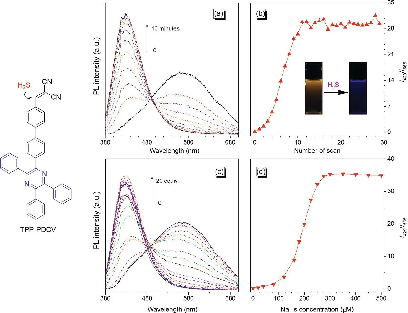
Figure 1.1 Fluorescent detection of H 2S by TPP‐PDCV. (a) Time‐dependent PL spectra of TPP‐PDCV (25 μM) in the DMSO/PBS buffer mixture (v/v = 9 : 1) in the presence of NaHS (250 μM). (b) Plot of the relative PL intensity ( I 429/ I 565) versus the number of scan in 25 minutes, where I 429and I 565are the PL intensity at 429 and 565 nm, respectively. Inset: the photographs of the TPP‐PDCV solution before and after the addition of NaHS taken under an irradiation of a 356 nm UV light. (c) PL spectra of TPP‐PDCV in the DMSO/PBS buffer mixture (v/v = 9 : 1) with different NaHS concentrations (0–500 μM). (d) Plot of the relative PL intensity ( I 429/ I 565) versus NaHS concentration. For all the tests, the excitation wavelength is 372 nm.
The sensor can analyze the H 2S quantificationally. For example, the sensor possesses a response with the NaHS concentration range from 0 to 250 μM. However, in the concentration range of 0–75 and 150–225 μM, the linear responses can be observed, thus providing a platform to detect H 2S at low concentration ( Figure 1.1). Besides, the sensor shows a good selectivity against other anions (e.g. AcO −, F −, ClO −, IO 4 −, N 3 −, NO 2 −, and OH −, etc.), except for CO 3 2−, which exerts subtle effect on the detection. The biothiols of cysteine, homocysteine, and glutathione also pose some effect because of the presence of thiol in the structures. However, such an influence can be neglected in comparison to the strong signal in the presence of H 2S.
Study on the influence of molecular structure on the sensing property is particularly valuable to provide the clues for designing advanced functional materials. With this regard, Tang prepared three conjugated isomers of TPP‐ p ‐TPE, TPP‐ m ‐TPE, and TPP‐ o ‐TPE by connecting TPP and triphenylethene at the para‐, meta‐, and ortho‐positions, respectively ( Figure 1.2a) [55]. The isomers show the AIE effect due to the melding of the typical AIEgens of TPP and triphenylethene in the structures. Their conformations evolve from an extended to a folded one due to the different linkages between two units, which makes the emissions blue‐shifted and luminescence efficiency to decrease gradually. It is reasonable because the molecular conjugation gets worse as the structure changes.
Interestingly, TPP‐ o ‐TPE is an easy‐to‐form organic porous crystal thanks to its fold conformation locked by the strong intramolecular C–H···N hydrogen bond. It is an easy‐to‐form DCM‐captured porous crystal ( Figure 1.2b). In the crystal, every four molecules coordinately generate a cylinder‐like pore with a volume of around 0.27 nm 3, which is enough for accommodating two DCM molecules. The pores are distributed uniformly in the crystal and connected in a straight line as long‐ranged nanochannels. The porous crystal produces a fixed framework structure regardless of the guest molecules. For example, each pore can also capture two THF molecules, with the structure of crystal less changed ( Figure 1.2c). However, the size of the pore is tunable to fit different volumes of guest molecules.
Читать дальшеИнтервал:
Закладка:
Похожие книги на «Handbook of Aggregation-Induced Emission, Volume 2»
Представляем Вашему вниманию похожие книги на «Handbook of Aggregation-Induced Emission, Volume 2» списком для выбора. Мы отобрали схожую по названию и смыслу литературу в надежде предоставить читателям больше вариантов отыскать новые, интересные, ещё непрочитанные произведения.


Обсуждение, отзывы о книге «Handbook of Aggregation-Induced Emission, Volume 2» и просто собственные мнения читателей. Оставьте ваши комментарии, напишите, что Вы думаете о произведении, его смысле или главных героях. Укажите что конкретно понравилось, а что нет, и почему Вы так считаете.