Rethinking Prototyping
Здесь есть возможность читать онлайн «Rethinking Prototyping» — ознакомительный отрывок электронной книги совершенно бесплатно, а после прочтения отрывка купить полную версию. В некоторых случаях можно слушать аудио, скачать через торрент в формате fb2 и присутствует краткое содержание. Жанр: unrecognised, на английском языке. Описание произведения, (предисловие) а так же отзывы посетителей доступны на портале библиотеки ЛибКат.
- Название:Rethinking Prototyping
- Автор:
- Жанр:
- Год:неизвестен
- ISBN:нет данных
- Рейтинг книги:3 / 5. Голосов: 1
-
Избранное:Добавить в избранное
- Отзывы:
-
Ваша оценка:
Rethinking Prototyping: краткое содержание, описание и аннотация
Предлагаем к чтению аннотацию, описание, краткое содержание или предисловие (зависит от того, что написал сам автор книги «Rethinking Prototyping»). Если вы не нашли необходимую информацию о книге — напишите в комментариях, мы постараемся отыскать её.
The Design Modelling Symposium Berlin 2013 would like to challenge the participants to reflect on the possibility of computational systems that bridge design phase and occupancy of buildings. This rethinking of the designed artifact beyond its physical has had profound effects on other industries already. How does it affect architecture and engineering?
At the scale of engineering and building systems new perspectives may open up by engaging built form as a continuous prototype, which can track and respond during use and serve as a real world implementation of its design model. This has been tried many times from intelligent façades to smart homes and networked grids but much of it was only technology driven and not approached from a more holistic design perspective.
Rethinking Prototyping — читать онлайн ознакомительный отрывок
Ниже представлен текст книги, разбитый по страницам. Система сохранения места последней прочитанной страницы, позволяет с удобством читать онлайн бесплатно книгу «Rethinking Prototyping», без необходимости каждый раз заново искать на чём Вы остановились. Поставьте закладку, и сможете в любой момент перейти на страницу, на которой закончили чтение.
Интервал:
Закладка:
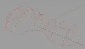
Fig. 9 Wireframe geometry
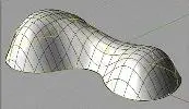
Fig. 10 NURBS patch
2.4 Shape Optimisation
For now, we built a space sketch of the project. However, this NURBS surface has no reason to lead directly to a structural shape. Thus, the structural elements have to be checked to make sure they will support the stress field induced by grid shaping.
Stress & Curvature
Stresses in elements are mainly due to grid bending, that is to say geometric curvature imposes the grid stress state (Eq. 1). Thus, principal curvatures of the surface describing the shape are good indicators to evaluate if the structural members have the required mechanical properties. This preliminary control can be completed by an analysis of the curvature of the mesh elements. Finally, nothing but a true structural analysis considering members mechanical properties will allow us to find the exact relaxed shape and the stress field in the structure.

(1)
Where σ represents the total stress (compressive plus bending) induced by the shaping. E , v and I are respectively the longitudinal young modulus, the radius and the bending inertia of the profile. R is the radius of curvature of the profile.
Surface Optimisation
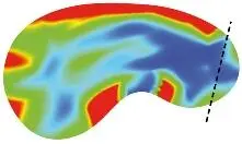
Before any attempt to mesh the shape, it is recommended to optimize the sketch shape regarding its minimal principal curvatures (Eq. 2). Using the curvature-analysis built-in function in Rhino it is easy to identify and smooth areas that are initially too curved (Fig. 11).

(2)
Different sketches are compared according to this criterion to smooth areas where curvature is excessive.

Sketch n°1

Sketch n°2
Sketch n°3
Fig. 11 Geometric curvature minimisation in three steps. Rmin ϵ [blue = 3,00m; red = 10,00m]
2.5 Shape Meshing
Following a decade of research on this topic at the Navier Laboratory , a specific tool has been developed on Rhino & Grasshopper for the design of such shape-driven gridshells (Fig. 12). This tool gathers several components that process basic operations (meshing with the compass method, grid-processing, structural analysis) required for the generation of a suitable grid for the materialization of a 3D shape by a gridshell structure.
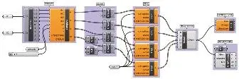
Fig. 12 Grasshopper canvas (compass method, grid processing, structural model generation)
Compass Method
This process propagates a two-way mesh of constant pitch on any NURBS surface.
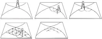
Fig. 13 Compass method principle
Two crossing guide-curves are drawn on the surface to mesh. These curves mark the boundary of four quarters. Each half guide-curve is then subdivided with a compass of constant distance w (the pitch). Finally, from two consecutive half guide-curves, quadrants are meshed with the same compass distance (Fig. 13).
Meshed Surface
The compass method does not allow meshing the entire meshing domain. Only a smaller part could be meshed and its area varies according the chosen set of guide-curves (Figs. 14-15). Thus, it is not possible to rely exclusively on the shape to be realized with the lattice. An extended surface - chosen carefully - has to be considered as the meshing domain.
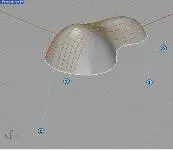
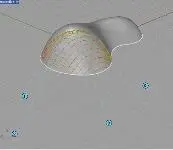
Fig. 14 Two different meshes are obtained from two distinct sets of guide-curves. The meshed area never takes on the whole surface. Convergence phenomena could be observed (right picture).
Overall Process
To overcome this difficulty we propose a methodology, which relies both on the creation of a meshing domain (domainSrf) from the targeted surface to materialise (gsSrf) and on the identification of a suitable set of guide-curves.
Step One
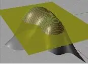
We consider the gridshell surface (gsSrf) a part of a larger surface (domainSrf). Trimmed by a clipping plane or surface (cuttingSrf), this domain surface should give back the intended shape to build (Figs. 15-16).
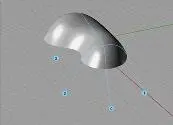
Fig. 15 gsSrf
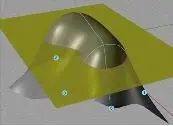
Fig. 16 domainSrf and cuttingSrf
Step Two
A set of guide-curves is chosen (Fig. 17) and the mesh is propagated on the domain surface according to the compass method (Fig. 18). The guide-curves have to be chosen so that the whole gridshell surface (gsSrf) is meshed. Several trials can be necessary to get a suitable mesh.
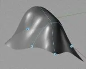
Fig. 17 Guide-curves set
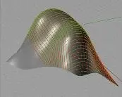
Fig. 18 Resulting mesh on domainSrf
Step Three
The mesh is trimmed by the clipping surface (Fig. 19). The resulting mesh lays on the whole initial intended surface to mesh. The gridshell support-outline is given by the intersection of the clipping plane and the domain surface (Fig. 20).
Интервал:
Закладка:
Похожие книги на «Rethinking Prototyping»
Представляем Вашему вниманию похожие книги на «Rethinking Prototyping» списком для выбора. Мы отобрали схожую по названию и смыслу литературу в надежде предоставить читателям больше вариантов отыскать новые, интересные, ещё непрочитанные произведения.


Обсуждение, отзывы о книге «Rethinking Prototyping» и просто собственные мнения читателей. Оставьте ваши комментарии, напишите, что Вы думаете о произведении, его смысле или главных героях. Укажите что конкретно понравилось, а что нет, и почему Вы так считаете.