Magnetic Resonance Microscopy
Здесь есть возможность читать онлайн «Magnetic Resonance Microscopy» — ознакомительный отрывок электронной книги совершенно бесплатно, а после прочтения отрывка купить полную версию. В некоторых случаях можно слушать аудио, скачать через торрент в формате fb2 и присутствует краткое содержание. Жанр: unrecognised, на английском языке. Описание произведения, (предисловие) а так же отзывы посетителей доступны на портале библиотеки ЛибКат.
- Название:Magnetic Resonance Microscopy
- Автор:
- Жанр:
- Год:неизвестен
- ISBN:нет данных
- Рейтинг книги:4 / 5. Голосов: 1
-
Избранное:Добавить в избранное
- Отзывы:
-
Ваша оценка:
Magnetic Resonance Microscopy: краткое содержание, описание и аннотация
Предлагаем к чтению аннотацию, описание, краткое содержание или предисловие (зависит от того, что написал сам автор книги «Magnetic Resonance Microscopy»). Если вы не нашли необходимую информацию о книге — напишите в комментариях, мы постараемся отыскать её.
Explore the interdisciplinary applications of magnetic resonance microscopy in this one-of-a-kind resource Magnetic Resonance Microscopy: Instrumentation and Applications in Engineering, Life Science and Energy Research,
Magnetic Resonance Microscopy: Instrumentation and Applications in Engineering, Life Science and Energy Research
Magnetic Resonance Microscopy: Instrumentation and Applications in Engineering, Life Science and Energy Research
Magnetic Resonance Microscopy — читать онлайн ознакомительный отрывок
Ниже представлен текст книги, разбитый по страницам. Система сохранения места последней прочитанной страницы, позволяет с удобством читать онлайн бесплатно книгу «Magnetic Resonance Microscopy», без необходимости каждый раз заново искать на чём Вы остановились. Поставьте закладку, и сможете в любой момент перейти на страницу, на которой закончили чтение.
Интервал:
Закладка:
3.5.1.3 Shorter Supercon Magnets from Relaxed Homogeneity
Because the optimization used by Xu and others is convex, it represents a true optimal solution and we must relax other constraints in order to achieve shorter magnets. In the text that follows, we replicate Xu et al.’s analysis [102] for L optimalas a function of DSV and magnet diameter for a D = 1.1 m magnet but also examined optimized designs with homogeneity targets between 1 ppm and 10 000 ppm. Figure 3.6 shows the result of this analysis. When a length-optimized design is chosen from the knee of the cost vs. length L -curve, the cost of an optimized design can be plotted as a function of the unitless L/DSV for a given homogeneity target. Figure 3.6 shows this result, which informs the potential improvements in magnet length achievable if imaging could be performed in less homogeneous fields. Unfortunately, substantial relaxation in homogeneity is needed to get a significant reduction in magnet length. For example, relaxing the 1 ppm specification to 1000 ppm reduces the magnet length from 2.92 to 2.15 in normalized units – a 26% reduction. Thus, superconducting solenoid magnets, as they are currently envisioned, are not likely to significantly change in geometry.
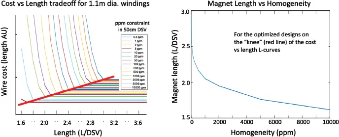
Figure 3.6 Tradeoffs in superconducting solenoid optimizations following the optimization of Xu et al.[] The wire cost is seen to rise significantly as the magnet length is shortened (here shown in units of the imaging volume diameter).The left graph shows the wire length–length tradeoff for different homogeneity constraints. Taking the points on the “knee” of these L -curves allows the plot of magnet length vs. homogeneity (right-hand graph).
3.5.1.4 Permanent Magnets for Portable MRI
Superconducting solenoids are attractive because of their lack of an external energy source, high stored magnetic field energy, and temporal stability, although with the requirement for a cryogenic subsystem. Permanent magnets offer these capabilities to some degree and do not need cryogenics. Their downside is a reduced field-generating capability; human-sized homogeneous magnets above 0.5 T require a considerable weight of material. They are also less stable, for example drifting with temperature.
Rare-earth magnets made from alloys of neodymium such as NdFeB are the strongest form of permanent magnets readily available. They are a relatively recent development, introduced in 1984 [104,105]. Formed into blocks from sintered powder and then magnetized by applying a pulsed magnetic field, the strength of the permanent magnet is measured by its remanence ( B r), which measures the magnetic field of the residual magnetization present in the absence of an external field. For NdFeB, B rranges from 1.0 to 1.4 T. The field of NdFeB changes with temperature, with a temperature coefficient of remanence of about −0.1% per °K (the field goes down as the temperature increases). The coercivity ( H cl) measures the material’s resistance to demagnetization by an external field (or the field of a neighboring block). The tendency of the sintered material to corrode requires that the block be coated, usually with copper-nickel plating, or a coating of epoxy or another polymer. Because of the considerable forces between large NdFeB blocks, handling and assembling the material requires care and expertise.
The most common geometry for MRI use is a simple two-pole-piece dipole magnet. Spacing two magnetized disks with a gap (containing the imaging region) forms a uniform dipole field volume between the pole pieces. Each disk creates a dipole current pattern, and the net effect is like two stacked current loops (each with the current flowing in the same sense). Optimizing the placement of the material in the disks and/or shaping an iron pole-piece can improve homogeneity. Adding an iron yoke helps channel the flux into a closed circuit and can provide mechanical support for the two disks (which otherwise want to come together). This is the basic configuration of many commercial 0.2–0.35-T “low-field open” MRI systems, which reached a peak in popularity in the early 1990s. The “open” patient space reduced claustrophobia anxieties at a time when superconducting solenoid systems were quite long and narrow bore (55 cm diameter as opposed to the current norm of 70 cm diameter). In many ways, low-field open systems remain a reasonable choice for emergency MR, but their size and weight are comparable with 1.5-T superconducting systems, requiring a similar siting footprint. The Hyperfine 64-mT portable MRI system [36] appears to follow this geometry, as does a 0.2-T portable system mounted in a mini-van for elbow imaging at baseball games [16]. The direction of the B 0field differs from their superconducting cousins. The superconducting solenoid imposes B 0in the “head–foot” direction, while low-field open systems usually have a posterior to anterior (vertical) B 0. It has been noted that the accompanying change in radiofrequency field geometry for low-field open geometry systems yields a reduced interaction with deep-brain stimulation leads (and lower radiofrequency heating) [106].
3.5.1.5 Halbach Arrays for Portable MRI
The standard dipole magnet described in Section 3.5.1.4, built by placing two blocks of magnetized material above and below the imaging volume can be extended by adding additional blocks around the imaging volume with intermediate magnetization angles. This extension is analogous to expanding two current loop coil dipoles in the “Helmholtz” configuration to a birdcage style structure by adding loops in a circular configuration with the currents phased at intermediate phase angles. In the permanent magnet case, the result is a magnetized annulus commonly referred to as a Halbach array shown in Figure 3.7 [107,108]. The ideal Halbach configurations have the counterintuitive property of not needing a flux return yoke because the flux is returned in the magnets themselves. In linear Halbach arrays there is no flux on one side of the structure. Similarly, the ideal cylindrical (Figure 3.7, top left) and spherical Halbach arrays have no flux outside the structure [109]. This nearly completely eliminates the stray-field footprint, as well as eliminating the heavy iron yoke associated with the open-MRI dipole magnets; two compelling practical advantages to the Halbach configurations.
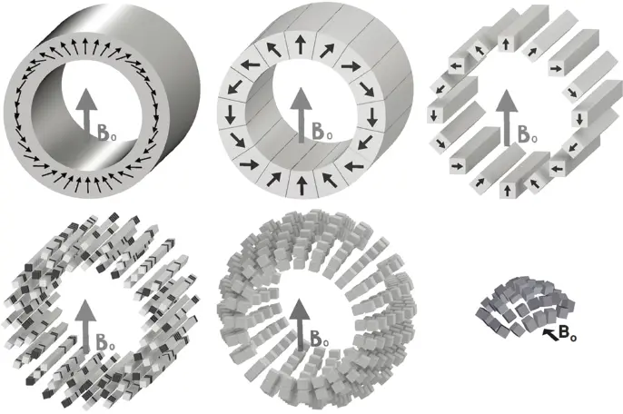
Figure 3.7 Halbach arrays of permanent magnets. Phasing the magnetization from 0 to 4π provides a magnetic dipole with a uniform transverse field inside. Higher-order modes can be obtained by varying the angle to other multiples of 2π. Top left shows the ideal continuous magnetization distribution. Top middle uses key-stone shaped pieces. Top right shows square cross-section pieces, which are readily commercially available. Bottom left shows the possibility of using multiple cubes of differing B r, chosen to optimize a desired field pattern. The bottom middle takes better advantage of the head geometry by using a portion of a Halbach sphere. The bottom right shows a section of a Halbach sphere used in the “MR Cap” of Figure 3.3.
The field inside an ideal cylindrical Halbach array (e.g. Figure 3.7, top left) of inner radius r aand outer radius r bis given by B = B rln( r b/ r a), where B ris the remanence of the material used. Thus, for a human head system with r b/ r a= 50 cm/30 cm and B r= 1.4 T, we can expect a field of B 0= 0.72 T in this ideal structure. For a whole-body system with r b/ r a= 120 cm/80 cm, B 0= 0.56 T. If the cylinder length is not infinite, but equal to its outer diameter, the estimated weight of rare-earth material for these two systems would be 1500 kg and 18 000 kg – not exactly lightweight. Achieving realistic weights for POC systems necessitates reducing the field, typically to below 0.1 T for adult human imaging systems.
Читать дальшеИнтервал:
Закладка:
Похожие книги на «Magnetic Resonance Microscopy»
Представляем Вашему вниманию похожие книги на «Magnetic Resonance Microscopy» списком для выбора. Мы отобрали схожую по названию и смыслу литературу в надежде предоставить читателям больше вариантов отыскать новые, интересные, ещё непрочитанные произведения.


Обсуждение, отзывы о книге «Magnetic Resonance Microscopy» и просто собственные мнения читателей. Оставьте ваши комментарии, напишите, что Вы думаете о произведении, его смысле или главных героях. Укажите что конкретно понравилось, а что нет, и почему Вы так считаете.