Magnetic Resonance Microscopy
Здесь есть возможность читать онлайн «Magnetic Resonance Microscopy» — ознакомительный отрывок электронной книги совершенно бесплатно, а после прочтения отрывка купить полную версию. В некоторых случаях можно слушать аудио, скачать через торрент в формате fb2 и присутствует краткое содержание. Жанр: unrecognised, на английском языке. Описание произведения, (предисловие) а так же отзывы посетителей доступны на портале библиотеки ЛибКат.
- Название:Magnetic Resonance Microscopy
- Автор:
- Жанр:
- Год:неизвестен
- ISBN:нет данных
- Рейтинг книги:4 / 5. Голосов: 1
-
Избранное:Добавить в избранное
- Отзывы:
-
Ваша оценка:
Magnetic Resonance Microscopy: краткое содержание, описание и аннотация
Предлагаем к чтению аннотацию, описание, краткое содержание или предисловие (зависит от того, что написал сам автор книги «Magnetic Resonance Microscopy»). Если вы не нашли необходимую информацию о книге — напишите в комментариях, мы постараемся отыскать её.
Explore the interdisciplinary applications of magnetic resonance microscopy in this one-of-a-kind resource Magnetic Resonance Microscopy: Instrumentation and Applications in Engineering, Life Science and Energy Research,
Magnetic Resonance Microscopy: Instrumentation and Applications in Engineering, Life Science and Energy Research
Magnetic Resonance Microscopy: Instrumentation and Applications in Engineering, Life Science and Energy Research
Magnetic Resonance Microscopy — читать онлайн ознакомительный отрывок
Ниже представлен текст книги, разбитый по страницам. Система сохранения места последней прочитанной страницы, позволяет с удобством читать онлайн бесплатно книгу «Magnetic Resonance Microscopy», без необходимости каждый раз заново искать на чём Вы остановились. Поставьте закладку, и сможете в любой момент перейти на страницу, на которой закончили чтение.
Интервал:
Закладка:
Siting a small footprint MRI in the NICU would provide tangible benefits and a bedside (portable) MRI could offer additional benefits. Figure 3.5 illustrates some existing MRI systems and components that have been developed or adapted for MRI in the NICU. The benefits of bedside MRI accrue since even the trip from one side of the NICU to the other is difficult due to the removal/replacement of leads, tubes, ventilation, and temperature maintenance equipment. Furthermore, intravenous (IV) pumps are not MR compatible so extension tubing must be placed, which can interrupt the administration of critical medications (e.g. dopamine). Even if “MR-safe,” noncompatible or metallic equipment can cause susceptibility artifacts, which are more severe at higher field strengths [79]. All of these issues point to an extremely compact magnetic footprint magnet; likely a mid- to low-field magnet design with minimal fringe field.
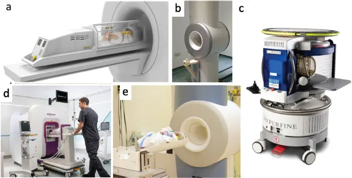
Figure 3.5 MR devices designed to support imaging in neonatal intensive care unit (NICU). (a) LMT MRI compatible incubator (LMT Medical Systems GmbH). (b) GE Healthcare investigational 3-T neonatal MR system installed at Sheffield Teaching Hospital in a dedicated NICU scan room (EMAP Publishing Limited). (c) The Hyperfine 64-mT portable MRI scanner. (d) Aspect Imaging’s Embrace neonatal scanner, a dedicated 1-T permanent magnet scanner designed for installation in the NICU without a shielded room. (e) Modified 1.5-T GE orthopedic scanner adapted for the NICU at Cincinnati Children’s Hospital.
3.5 Technological Approaches to POC and/or Portable MRI
The goal of reducing cost, siting needs, and even enabling portability has resurrected interest in low-field MRI technology, including new magnet and encoding methods. Low-field MRI, loosely defined as scanners operating between 10 mT and 500 mT, has a long history in MRI, starting with the first human imaging systems [80–83]. Although high-field superconducting magnet-equipped scanners have largely displaced them, thousands of low-field MRI systems (mainly in the 0.2–0.35-T range) are in daily operation and their clinical capabilities are well known. Additionally, commercial systems operating below 100 mT have an established clinical history; for example, the Toshiba Access 64-mT system introduced in 1991. These older generation low-field systems are often called “open MRIs” due to the two-pole-piece dipole magnet geometry used. They are still big and heavy and have most of the siting issues of their high-field superconducting cousins. This review focuses on the modern generation of low-field scanners specifically aimed at the three POC uses outlined earlier. The “low” vs. “ultralow” tradeoffs have been recently reviewed in depth [84].
In addition to low-field architectures, considerable research has also focused on ultralow field (ULF), with B 0below 10 mT [85]. However, several barriers remain to using ULF approaches to achieve low-cost or POC and/or portable medical imaging. The sensitivity of MR as a function of field strength is well known [18], and the severe penalty at ULF requires either additional technology such as prepolarization [86], cryogenic detectors [87–90], hyperpolarized media [91], or efficient but nonstandard brain-imaging sequence schemes [92]. This additional technology can be a barrier to achieving reduced costs or portability. Additional issues arise for image encoding at ULF due to unwanted encoding by the gradient coil’s concomitant field terms [93,94].
Because of the signal-to-noise ratio limitations of ULF MRI, this review focuses mainly on compact magnets with B 0of above 50 mT or compact superconducting magnets in the 0.5–1.0-T range. We focus on magnet and system architecture and component technology; the constraints of MR physics at low field are well understood and are discussed in several recent reviews [15,18,19,84,95,96].
3.5.1 Magnet Designs
3.5.1.1 Advances in Cryogenics for Supercon Magnets
Recent advances have been made in cryogenic technology that facilitate maintenance and siting of superconducting high- and mid-field MRI systems in diverse locations. Modern cryocoolers can now remove more heat than previous generations allowing reduction and even elimination of the “bath” of liquid helium (LHe) that has typically surrounded the superconducting wire in the magnet to maintain it at 4.2 K. These cryogenic technologies and those leading up to them have been extensively reviewed [97]. In the earliest superconducting magnets, a two-cryogen system was used; LHe on the inner vessel providing a liquid bath in direct contact with the niobium titanium (NbTi) superconducting wire, and liquid nitrogen (LN) in an outer vessel to reduce heat flow to the environment. The residual heat entering the LHe vessel was countered only by the latent heat of evaporation of helium, about 20.5 kJ/kg. Thus, boiling off ~8 l of Lhe per day (~1 kg per day) compensates for a heat leak of only 0.24 W. The next step was to replace the use of nitrogen with a mechanical refrigeration system (“cold-head”). This is considerably safer, since nitrogen gas poses increased asphyxiation risk compared with helium (which floats up rather than sinking down). In addition to being more convenient, holding a radiation shields outside of the LHe vessel to 20 K and 70 K using cold-heads also decreases the heat flow compared with a similar 77 K LN cooled surface.
Superconducting MRI systems typically employ Gifford–McMahon (GM) cryocoolers, a variant of the older Stirling cycle. GM cryocoolers have a moving rotary valve in the subsystem attached to the magnet, which makes the familiar steady “washing machine” sound of a nonscanning MRI, and is also a potential source of failure and mechanical vibrations. Current cold-heads can achieve more than 1 W of cooling at 4.2 K and tens of Watts at 12 K. This is enough to not only lessen the entering heat flux, but to fully overcome it, allowing GM cryocooler technology to provide sufficient heat removal at 4 K that helium is liquefied inside the cryostat. The result is a “zero-boiloff” magnet, now the norm for new clinical MRI systems. While not a fully “dry magnet,” current zero-boiloff designs eliminate the need for regular cryogen fills.
The next step is to eliminate the LHe completely, or at least reduce LHe volume to where the system can be safely operated without an emergency quench vent system (<10 l of LHe). This can save significantly on siting costs, especially in a complex hospital setting such as the ED. Elimination of most of the LHe bath requires direct “conduction cooling” of the superconductor by the cold-head (as opposed to bathing the windings in LHe). Although first envisioned as needing more exotic higher temperature superconductors such MgB 2[98,99], “dry magnets” have recently been introduced by the major clinical MRI manufacturers using standard NbTi wire. The use of high-temperature superconductors that operate well above 4.2 K is attractive because they have an easier cooling target but is currently held back by their increased cost.
3.5.1.2 Superconducting Solenoid Designs for the Easy-to-Site Suite
Shorter superconducting solenoid magnets have clear benefits for patient acceptance and ease of siting and use in an ED setting. In contrast to the situation for cryogenic equipment, the design of superconducting MRI magnet windings is little changed over the past few decades; see Lvovsky et al. for a thorough review [97]. In standard design optimizations, the position and number of turns of discrete winding groups are optimized on the cylinder. In addition to the primary field-producing windings, counter-wound shielding windings (usually larger-diameter coils at the bore end) attempt to reduce the stray field around the magnet. The optimization seeks a short magnet on a predetermined diameter cylindrical former that achieves the target homogeneity over the imaging region (typically defined as a given diameter spherical volume (DSV) with a minimum wire cost (length of wire). The optimization either assumes a small number of winding groups (e.g. six) [100] or uses linear programming and a sparsity-promoting norm to limit the winding groups [101]. The magnet homogeneity is a relative measure (ppm) and expressing the magnet length in unitless terms (as L /DSV, where DSV is the imaging “diameter spherical volume”) is also helpful. Xu et al. [102] showed that for a 1 ppm target homogeneity, the cost-optimized magnets followed a linear formula: L optimal= 1.19 DSV + 0.77 D , where L optimaland D are the magnet windings length and diameter, and DSV is the diameter of the spherical homogeneity region. Reducing the magnet length further (< L optimal) results in skyrocketing wire costs (which are proportional to conductor volume). A similar analysis was also applied to gradient coil lengths [103].
Читать дальшеИнтервал:
Закладка:
Похожие книги на «Magnetic Resonance Microscopy»
Представляем Вашему вниманию похожие книги на «Magnetic Resonance Microscopy» списком для выбора. Мы отобрали схожую по названию и смыслу литературу в надежде предоставить читателям больше вариантов отыскать новые, интересные, ещё непрочитанные произведения.


Обсуждение, отзывы о книге «Magnetic Resonance Microscopy» и просто собственные мнения читателей. Оставьте ваши комментарии, напишите, что Вы думаете о произведении, его смысле или главных героях. Укажите что конкретно понравилось, а что нет, и почему Вы так считаете.