Philip Hofmann - Solid State Physics
Здесь есть возможность читать онлайн «Philip Hofmann - Solid State Physics» — ознакомительный отрывок электронной книги совершенно бесплатно, а после прочтения отрывка купить полную версию. В некоторых случаях можно слушать аудио, скачать через торрент в формате fb2 и присутствует краткое содержание. Жанр: unrecognised, на английском языке. Описание произведения, (предисловие) а так же отзывы посетителей доступны на портале библиотеки ЛибКат.
- Название:Solid State Physics
- Автор:
- Жанр:
- Год:неизвестен
- ISBN:нет данных
- Рейтинг книги:4 / 5. Голосов: 1
-
Избранное:Добавить в избранное
- Отзывы:
-
Ваша оценка:
Solid State Physics: краткое содержание, описание и аннотация
Предлагаем к чтению аннотацию, описание, краткое содержание или предисловие (зависит от того, что написал сам автор книги «Solid State Physics»). Если вы не нашли необходимую информацию о книге — напишите в комментариях, мы постараемся отыскать её.
Solid State Physics
Solid State Physics
Solid State Physics
Solid State Physics — читать онлайн ознакомительный отрывок
Ниже представлен текст книги, разбитый по страницам. Система сохранения места последней прочитанной страницы, позволяет с удобством читать онлайн бесплатно книгу «Solid State Physics», без необходимости каждый раз заново искать на чём Вы остановились. Поставьте закладку, и сможете в любой момент перейти на страницу, на которой закончили чтение.
Интервал:
Закладка:
It is highly beneficial to use the complex notation for describing the electromagnetic X‐ray waves. For the electric field, a general plane wave can be written as
(1.4) 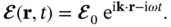
The wave vector  points in the direction of the wave propagation with a length of
  , where
  is the wavelength. The convention is that the physical electric field is obtained as the real part of the complex field and the intensity of the wave is obtained as
(1.5) 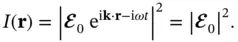
Consider now the situation depicted in Figure 1.10. The source of the X‐rays is far away from the sample at the position  so that the X‐ray wave at the sample can be described as a plane wave. The electric field at a point
  in the crystal at time
  can be written as
(1.6) 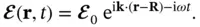
Before we proceed, we can drop the absolute amplitude  from this expression because we are only interested in relative phase changes. The field at point
  is then
(1.7) 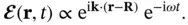
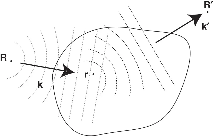
Figure 1.10 Illustration of X‐ray scattering from a sample. The source and detector for the X‐rays are placed at  and
and  , respectively. Both are very far away from the sample.
A small volume element  located at
  will give rise to scattered waves in all directions. The direction we are interested in is that towards the detector, which we assume to be placed at position
  , in the direction of a second wave vector
  . We assume that the amplitude of the wave scattered in this direction will be proportional to the incoming field from Eq. (1.7)and to a factor
  describing the scattering probability and scattering phase. We already know that the scattering of X‐rays proceeds via the electrons in the material, and for our purpose, we can view
  as the electron concentration in the solid. For the field at the detector, we obtain
(1.8) 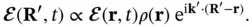
Again, we have assumed that the detector is very far away from the sample so that the scattered wave at the detector can be written as a plane wave. Inserting Eq. (1.7)gives the field at the detector as
(1.9) 
We drop the first factor that does not contain  and will thus not play a role for the interference of X‐rays emitted from different positions in the sample. The total wave field at the detector can finally be calculated by integrating over the entire volume
  of the crystal. As the detector is far away from the sample, the wave vector
  is essentially the same for all points in the sample. The result is therefore
(1.10) 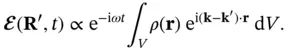
In most cases, it will only be possible to measure the intensity of the X‐rays and not the field amplitude. This intensity is given by
(1.11) 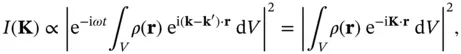
where we have introduced the so‐called scattering vector  , which is just the difference of the outgoing and incoming wave vectors. Note that although the direction of the wave vector
  for the scattered waves is different from that of the incoming wave
  , their lengths are the same because we consider elastic scattering only.
Интервал:
Закладка:
Похожие книги на «Solid State Physics»
Представляем Вашему вниманию похожие книги на «Solid State Physics» списком для выбора. Мы отобрали схожую по названию и смыслу литературу в надежде предоставить читателям больше вариантов отыскать новые, интересные, ещё непрочитанные произведения.


Обсуждение, отзывы о книге «Solid State Physics» и просто собственные мнения читателей. Оставьте ваши комментарии, напишите, что Вы думаете о произведении, его смысле или главных героях. Укажите что конкретно понравилось, а что нет, и почему Вы так считаете.