Mark Middlebrook - AutoCAD 2005 for Dummies
Здесь есть возможность читать онлайн «Mark Middlebrook - AutoCAD 2005 for Dummies» — ознакомительный отрывок электронной книги совершенно бесплатно, а после прочтения отрывка купить полную версию. В некоторых случаях можно слушать аудио, скачать через торрент в формате fb2 и присутствует краткое содержание. Город: Indianapolis, Год выпуска: 2004, ISBN: 2004, Издательство: Wiley Publishing, Inc, Жанр: Программы, на английском языке. Описание произведения, (предисловие) а так же отзывы посетителей доступны на портале библиотеки ЛибКат.

- Название:AutoCAD 2005 for Dummies
- Автор:
- Издательство:Wiley Publishing, Inc
- Жанр:
- Год:2004
- Город:Indianapolis
- ISBN:0-7645-7138-9
- Рейтинг книги:5 / 5. Голосов: 1
-
Избранное:Добавить в избранное
- Отзывы:
-
Ваша оценка:
AutoCAD 2005 for Dummies: краткое содержание, описание и аннотация
Предлагаем к чтению аннотацию, описание, краткое содержание или предисловие (зависит от того, что написал сам автор книги «AutoCAD 2005 for Dummies»). Если вы не нашли необходимую информацию о книге — напишите в комментариях, мы постараемся отыскать её.
AutoCAD is more than just another application program, it’s a complete environment for drafting and design. So if you’re new to AutoCAD, you need to know several things to get off to a good start — especially how to use the command line area and set up your drawing properly. These key techniques are described in this part of the book.
If you’ve used earlier versions of AutoCAD, you’ll be most interested in the high points of the new release, including some newer interface components. The lowdown on what’s new is here, too.
AutoCAD 2005 for Dummies — читать онлайн ознакомительный отрывок
Ниже представлен текст книги, разбитый по страницам. Система сохранения места последней прочитанной страницы, позволяет с удобством читать онлайн бесплатно книгу «AutoCAD 2005 for Dummies», без необходимости каждый раз заново искать на чём Вы остановились. Поставьте закладку, и сможете в любой момент перейти на страницу, на которой закончили чтение.
Интервал:
Закладка:
CAD precision usually helps produce accurate drawings, but that’s not always the case. You can produce a precise CAD drawing that’s inaccurate because you started from inaccurate information (for example, the contractor gave you a wrong field measurement). Or you might deliberately exaggerate certain distances to convey the relationship between objects more clearly on the plotted drawing. Even where you must sacrifice accuracy, aim for precision.
In CAD, lack of precision makes later editing, hatching, and dimensioning tasks much more difficult and time consuming:
□ Small errors in precision in the early stages of creating or editing a drawing often have a big effect on productivity and precision later.
□ Drawings may guide manufacturing and construction projects; drawing data may drive automatic manufacturing machinery. Huge amounts of money, even lives, can ride on a drawing’s precision.
In recognition of this, a passion for precision permeates the profession. Permanently. Precision is one of the characteristics that separates CAD from ordinary illustration-type drawing work. The sooner you get fussy about precision in AutoCAD, the happier everyone is.
In the context of drawing objects, precision means specifying points and distances precisely, and AutoCAD provides a range of tools for doing so. Table 4-2 lists the more important AutoCAD precision techniques, plus the status bar buttons that you click to toggle some of the features off and on.
Table 4-2 Precision Techniques
| Technique | Status Bar | Button Description |
|---|---|---|
| Coordinate entry | — | Type exact X,Y coordinates. |
| Single-point object snaps | — | Pick points on existing objects (lasts for one point pick). |
| Running object snaps | OSNAP | Pick points on existing objects (lasts for multiple point picks). |
| Snap | SNAP | Pick points on an imaginary grid of equally spaced “hot spots.” |
| Ortho | ORTHO | Constrain the cursor to move at an angle of 0, 90, 180, or 270 degrees from the previous point. |
| Direct distance entry | — | Point the cursor in a direction and type a distance. |
| Object snap tracking | OTRACK | Helps the cursor locate points based on multiple object snap points. |
| Polar tracking | POLAR | Makes the cursor prefer certain angles. |
| Polar snap | — | Causes the cursor to prefer certain distances along polar tracking angles. |
 Precision is especially important when you’re drawing or editing geometry — the lines, arcs, and so on that make up whatever you’re representing in the CAD drawing. Precision placement usually is less important with notes, leaders, and other annotations that describe, not show.
 Before you draw objects, always check the status bar’s SNAP, ORTHO, POLAR, OSNAP, and OTRACK buttons and set the buttons according to your precision needs.
□ A button that looks pushed in indicates that the feature is on.
□ A button that looks popped up indicates that the feature is off.
The most direct way to enter points precisely is to type numbers at the command line. AutoCAD uses these keyboard coordinate entry formats:
□ Absolute rectangular coordinates in the form X , Y (for example: 7,4)
□ Relative rectangular coordinates in the form @ X , Y (for example: @3,2)
□ Relative polar coordinates in the form @ distance (for example: @6<45)
AutoCAD locates absolute rectangular coordinates with respect to the 0,0 point of the drawing — usually its lower-left corner. AutoCAD locates relative rectangular coordinates and relative polar coordinates with respect to the previous point that you picked or typed. Figure 4-10 demonstrates how to use all three coordinate formats to draw a pair of line segments that start at absolute coordinates 2,1; go 3 units to the right and 2 units up; then go 4 units at an angle of 60 degrees.
 AutoCAD also understands absolute polar coordinates in the form distance , but this format is almost never useful.
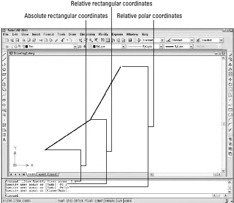
Figure 4-10:Coordinating from the keyboard.
You can view coordinate locations by moving the cursor around in the drawing area and reading the Coordinates area at the left of the status bar. The X,Y coordinates should change as you move the cursor. If the coordinates don’t change, click the Coordinates area until the command line says . Although it’s not apparent at first, there are in fact two display modes: absolute coordinates and polar coordinates. If you start a command such as LINE, pick a point, and then click the Coordinates area a few times, the display changes from coordinates off to live absolute coordinates (X,Y position) to live polar coordinates (distance and angle from the previous point). The live polar coordinates display mode is the most informative most of the time.
When you type coordinates at the command line, do not add any spaces, because AutoCAD interprets them as though you’ve pressed Enter. This “Spacebar=Enter” weirdness is a productivity feature that’s been in AutoCAD forever. It’s easier to find the spacebar than the Enter key when you’re entering lots of commands and coordinates in a hurry.
If you’re working in architectural or engineering units, the default unit of entry is inches, not feet.
□ To specify feet, you must enter the symbol for feet after the number, for example:
6’for 6 feet
□ You can enter a dash to separate feet from inches, as architects often do:
6’–6”is 6 feet, 6 inches.
□ Both the dash and the inch mark are optional when you’re entering coordinates and distances:
AutoCAD understands 6’6”and 6’6as the same as 6’–6”.
□ If you’re typing a coordinate or distance that contains fractional inches, you must enter a dash — not a space — between the whole number of inches and the fraction:
6’6–1/2(or 6’–6–1/2) represents 6 feet, 6½ inches.
□ If all this dashing about confuses you, enter partial inches by using decimals instead:
6’6.5is the same as 6’6–1/2to AutoCAD, whether you’re working in architectural or engineering units.
After you’ve drawn a few objects precisely in a new drawing, the most efficient way to draw more objects with equal precision is to grab points, such as endpoints, midpoints, or quadrants, on the existing objects. AutoCAD calls this object snapping , because the program pulls, or snaps , the cursor to a point on an existing object . The object snapping feature in general and object snap points in particular often are called osnaps .
Читать дальшеИнтервал:
Закладка:
Похожие книги на «AutoCAD 2005 for Dummies»
Представляем Вашему вниманию похожие книги на «AutoCAD 2005 for Dummies» списком для выбора. Мы отобрали схожую по названию и смыслу литературу в надежде предоставить читателям больше вариантов отыскать новые, интересные, ещё непрочитанные произведения.


Обсуждение, отзывы о книге «AutoCAD 2005 for Dummies» и просто собственные мнения читателей. Оставьте ваши комментарии, напишите, что Вы думаете о произведении, его смысле или главных героях. Укажите что конкретно понравилось, а что нет, и почему Вы так считаете.