Mark Middlebrook - AutoCAD 2005 for Dummies
Здесь есть возможность читать онлайн «Mark Middlebrook - AutoCAD 2005 for Dummies» — ознакомительный отрывок электронной книги совершенно бесплатно, а после прочтения отрывка купить полную версию. В некоторых случаях можно слушать аудио, скачать через торрент в формате fb2 и присутствует краткое содержание. Город: Indianapolis, Год выпуска: 2004, ISBN: 2004, Издательство: Wiley Publishing, Inc, Жанр: Программы, на английском языке. Описание произведения, (предисловие) а так же отзывы посетителей доступны на портале библиотеки ЛибКат.

- Название:AutoCAD 2005 for Dummies
- Автор:
- Издательство:Wiley Publishing, Inc
- Жанр:
- Год:2004
- Город:Indianapolis
- ISBN:0-7645-7138-9
- Рейтинг книги:5 / 5. Голосов: 1
-
Избранное:Добавить в избранное
- Отзывы:
-
Ваша оценка:
AutoCAD 2005 for Dummies: краткое содержание, описание и аннотация
Предлагаем к чтению аннотацию, описание, краткое содержание или предисловие (зависит от того, что написал сам автор книги «AutoCAD 2005 for Dummies»). Если вы не нашли необходимую информацию о книге — напишите в комментариях, мы постараемся отыскать её.
AutoCAD is more than just another application program, it’s a complete environment for drafting and design. So if you’re new to AutoCAD, you need to know several things to get off to a good start — especially how to use the command line area and set up your drawing properly. These key techniques are described in this part of the book.
If you’ve used earlier versions of AutoCAD, you’ll be most interested in the high points of the new release, including some newer interface components. The lowdown on what’s new is here, too.
AutoCAD 2005 for Dummies — читать онлайн ознакомительный отрывок
Ниже представлен текст книги, разбитый по страницам. Система сохранения места последней прочитанной страницы, позволяет с удобством читать онлайн бесплатно книгу «AutoCAD 2005 for Dummies», без необходимости каждый раз заново искать на чём Вы остановились. Поставьте закладку, и сможете в любой момент перейти на страницу, на которой закончили чтение.
Интервал:
Закладка:
6. Click OK to close the Drafting Settings dialog box.
 You can also click the SNAP button on the status bar to toggle snap on and off; the same goes for the GRID button and the grid setting.
You can set your grid spacing to work in one of two ways: to help with your drawing or to help you remain aware of how objects will relate to your plot. For a grid that helps with your drawing, set the grid points a logical number of measurement units apart. For example, you might set the grid to 30 feet (10 yards) on a drawing of a (U.S.) football field. This kind of setting makes your work easier as you draw.
Another approach is to choose a grid spacing that represents a specific distance, such as 1 inch or 25 millimeters, on your final plot. If you want the grid to represent 1 inch on the plot and your drawing units are inches, enter the drawing scale factor. For example, in a ¼”=1’–0” drawing, you’d enter the drawing scale factor of 48. A 48-inch grid interval in your drawing corresponds to a 1-inch interval on the plot when you plot to scale. If your drawing units are millimeters and you want the grid to represent 25 millimeters on the plot, enter the drawing scale factor times 25. For example, in a 1:50 drawing, you’d enter 25×50, or 1250.
In most cases, you’ll want to set the snap interval considerably smaller than the grid spacing. A good rule is to start with a snap spacing in the range of the size of the smallest objects that you’ll be drawing — 6 inches or 100 millimeters for a building plan, 0.5 inches or 5 millimeters for an architectural detail, 1⁄16 inch or 1 millimeter for a small mechanical component, and so on.
Leaving the grid on in your drawing all the time is worthwhile because it provides a visual reminder of how far apart things are. This visual reference is especially useful as you zoom in and out.
You don’t always want to leave snap turned on, however. Some drawings, such as contour maps, are made up mostly of objects with weird, uneven measurements. Even drawings with many objects that fall on convenient spacings will have some unruly objects that don’t. In addition, you sometimes need to turn off snap temporarily to select objects. Despite these caveats, snap is a useful tool in most drawings.
Setting the snap spacing to a reasonable value when you set up a new drawing is a good idea. Toggle snap off (by clicking the SNAP button on the status bar or pressing the F9 key) when you don’t need it or find that it’s getting in the way. Toggle snap on before drawing objects that align with specific spacings, including text and dimension strings that you want to align neatly
To use snap effectively, you need to make the snap setting smaller as you zoom in and work on more detailed areas, and larger as you zoom back out. You are likely to find yourself changing the snap setting fairly frequently. The grid setting, on the other hand, can usually remain constant even as you work at different zoom settings; that keeps you oriented as to how far zoomed in you are in the drawing.
Even though you’ve engraved the drawing scale factor on your desk and written it on your hand — not vice versa — AutoCAD doesn’t know the drawing scale until you enter it. Keeping AutoCAD in the dark is fine as long as you’re just drawing continuous lines and curves representing real-world geometry, because you draw these objects at their real-world size, without worrying about plot scale.
As soon as you start adding dimensions (measurements that show the size of the things you’re drawing) and using dash-dot linetypes (line patterns that contain gaps in them), you need to tell AutoCAD how to scale the parts of the dimensions and the gaps in the linetypes based on the plot scale. If you forget this, the dimension text and arrowheads can come out very tiny or very large when you plot the drawing, and dash-dot linetype patterns can look waaaay too big or too small. Figure 3-7 shows what I mean.
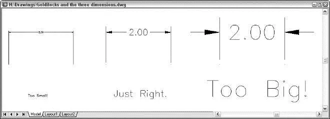
Figure 3-7:The dimension and linetype scales need to be just right.
The scale factor that controls dash-dot linetypes is found in a system variable called LTSCALE (as in LineType SCALE). The scaling factor that controls dimensions is found in a system variable called DIMSCALE.
You can change either of these settings at any time, but it’s best to set them correctly when you’re setting up the drawing.
The following sequence includes directions for typing system variable and command names. When the names are mixed case (for example, LTScale), you can type the full name ( LTSCALE) or just the letters shown in uppercase ( LTS) before pressing Enter.
To set the linetype scale from the command line, follow these steps:
1. TypeLTScale on the command line and press Enter.
AutoCAD responds with a prompt, asking you for the scale factor. The value at the end of the prompt is the current linetype scale setting, as in the following example:
Enter new linetype scale factor 1.0000:
2. Type the value you want for the linetype scale on the command line and press Enter.
The easiest choice is to set the linetype scale to the drawing scale factor. Some people (myself included) find that the dashes and gaps in dash-dot linetypes get a bit too long when they use the drawing scale factor. If you’re one of those people, set LTSCALE to one-half of the drawing scale factor.
 Alternatively, you can set LTSCALE in the Linetype Manager dialog box: Choose Format→Linetype, click the Show Details button, and type your desired linetype scale in the Global Scale Factor edit box.
To change the dimension scale, use the Dimension Style Manager dialog box. I describe dimensions in detail in Chapter 10, but you should get in the habit of setting the dimension scale during drawing setup. To do so, follow these steps:
1. Choose Format→Dimension Style from the menu bar, or enterDimstyle at the command line.
The Dimension Style Manager dialog box appears. New drawings contain the default dimension style named Standard (for English units drawings) or ISO25 (for metric drawings).
2. Click the Modify button.
The Modify Dimension Style dialog box appears.
3. Click the Fit tab.
The Fit tab options appear, including an area called Scale for Dimension Features.
4. In the Scale for Dimension Features area, make sure that the radio button next to the Use Overall Scale Of setting is selected.
5. In the text box next to Use Overall Scale Of, type the drawing scale factor for the current drawing.
I told you that you’d be using that drawing scale factor a lot!
6. Click OK to close the Modify Dimension Style dialog box.
The Dimension Style Manager dialog box reappears.
7. Click Close.
The Dimension Style Manager dialog box closes. Now when you draw dimensions (see Chapter 10), AutoCAD will scale the dimension text and arrowheads correctly.
Before you start creating dimensions, create your own dimension style(s) for the settings that you want to use. Chapter 10 explains why and how.
Интервал:
Закладка:
Похожие книги на «AutoCAD 2005 for Dummies»
Представляем Вашему вниманию похожие книги на «AutoCAD 2005 for Dummies» списком для выбора. Мы отобрали схожую по названию и смыслу литературу в надежде предоставить читателям больше вариантов отыскать новые, интересные, ещё непрочитанные произведения.


Обсуждение, отзывы о книге «AutoCAD 2005 for Dummies» и просто собственные мнения читателей. Оставьте ваши комментарии, напишите, что Вы думаете о произведении, его смысле или главных героях. Укажите что конкретно понравилось, а что нет, и почему Вы так считаете.