Mark Middlebrook - AutoCAD 2005 for Dummies
Здесь есть возможность читать онлайн «Mark Middlebrook - AutoCAD 2005 for Dummies» — ознакомительный отрывок электронной книги совершенно бесплатно, а после прочтения отрывка купить полную версию. В некоторых случаях можно слушать аудио, скачать через торрент в формате fb2 и присутствует краткое содержание. Город: Indianapolis, Год выпуска: 2004, ISBN: 2004, Издательство: Wiley Publishing, Inc, Жанр: Программы, на английском языке. Описание произведения, (предисловие) а так же отзывы посетителей доступны на портале библиотеки ЛибКат.

- Название:AutoCAD 2005 for Dummies
- Автор:
- Издательство:Wiley Publishing, Inc
- Жанр:
- Год:2004
- Город:Indianapolis
- ISBN:0-7645-7138-9
- Рейтинг книги:5 / 5. Голосов: 1
-
Избранное:Добавить в избранное
- Отзывы:
-
Ваша оценка:
AutoCAD 2005 for Dummies: краткое содержание, описание и аннотация
Предлагаем к чтению аннотацию, описание, краткое содержание или предисловие (зависит от того, что написал сам автор книги «AutoCAD 2005 for Dummies»). Если вы не нашли необходимую информацию о книге — напишите в комментариях, мы постараемся отыскать её.
AutoCAD is more than just another application program, it’s a complete environment for drafting and design. So if you’re new to AutoCAD, you need to know several things to get off to a good start — especially how to use the command line area and set up your drawing properly. These key techniques are described in this part of the book.
If you’ve used earlier versions of AutoCAD, you’ll be most interested in the high points of the new release, including some newer interface components. The lowdown on what’s new is here, too.
AutoCAD 2005 for Dummies — читать онлайн ознакомительный отрывок
Ниже представлен текст книги, разбитый по страницам. Система сохранения места последней прочитанной страницы, позволяет с удобством читать онлайн бесплатно книгу «AutoCAD 2005 for Dummies», без необходимости каждый раз заново искать на чём Вы остановились. Поставьте закладку, и сможете в любой момент перейти на страницу, на которой закончили чтение.
Интервал:
Закладка:
 The default Viewport scale, Scaled to Fit, ensures that all of your model drawing displays in the viewport but results in an arbitrary scale factor. Most technical drawings require a specific scale, such as 1=10 or ⅛”=1’–0”.
8. Specify the location of the viewport(s) on the paper by picking its corners. Then click Next.
After you click the Select Location button, the Create Layout Wizard displays the preliminary layout with any title block that you’ve chosen. Pick two points to define a rectangle that falls within the drawing area of your title block (or within the plottable area of the sheet, if you chose no title block in Step 6).
AutoCAD represents the plottable area of the sheet with a dashed rectangle near the edge of the sheet. If you don’t select a location for the viewport(s), the Create Layout Wizard creates a viewport that fills the plottable area of the sheet.
9. Click Finish.
AutoCAD creates the new layout.
 If your projects require lots of drawings, you can parlay layouts into sheet sets — a new feature in AutoCAD 2005 that makes for more sophisticated creation, management, plotting, and electronic transfer of multi-sheet drawing sets. See Chapter 14 for details.
After you create a layout, you can delete, copy, rename, and otherwise manipulate it by right-clicking its tab. Figure 3-11 shows the right-click menu options.
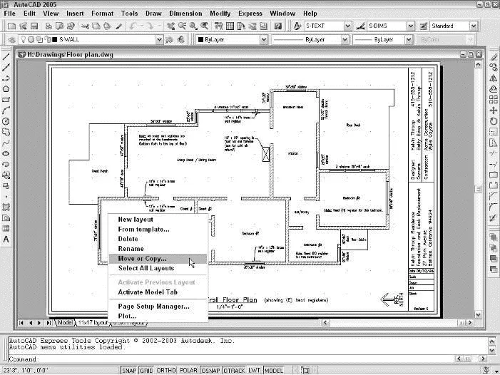
Figure 3-11:The rightclick menu for a layout tab.
 The From Template option refers to layout templates. After you create layouts in a template (DWT) or drawing (DWG) file, you use the From Template option to import these layouts into the current drawing. For details, see the LAYOUT command’s Template option in the Command Reference section of online help.
Many drawings require only one paper space layout. If you always plot the same view of the model and always plot to the same device and on the same size paper, a single paper space layout should suffice. If you want to plot your model in different ways (for example, at different scales, with different layers visible, with different areas visible, or with different plotted line characteristics), you may want to create additional paper space layouts.
Some different ways of plotting the same model can be handled in a single paper space layout with different page setups. See Chapter 12 for more details.
If you want to add another viewport to an existing layout, you need to become familiar with the MVIEW command and the ZOOM command’s mysterious XP option. See the MVIEW and ZOOM commands in the Command Reference section of AutoCAD online help. After you have the concepts down, using the Viewports dialog box (choose View→Viewports→New Viewports) and Viewports toolbar can help you create and manage viewports more efficiently.
After you create a paper space layout, you suddenly have two views of the same drawing geometry: the view on your original Model tab and the new layout tab view (perhaps decorated with a handsome title block and other accoutrements of plotting nobility). It’s important to realize that both views are of the same geometry. If you change the model geometry on one tab, you’re changing it on all tabs, because all tabs display the same model space objects. It’s like seeing double after downing a few too many drinks — the duplication is in your head, not in the real world (or in this case, in the CAD world).
When you make a paper space layout current by clicking its tab, you can move the cursor between paper space (that is, drawing and zooming on the sheet of paper) and model space (drawing and zooming on the model, inside the viewport) in several ways, including:
□ Clicking the PAPER/MODEL button on the status bar
□ In the drawing area, double-clicking over a viewport to move the cursor into model space in that viewport, or double-clicking outside all viewports (for example, in the gray area outside the sheet) to move the cursor into paper space
□ Entering MSpaceor PSpaceat the command prompt
When the cursor is in model space, anything you draw or edit changes the model (and thus appears on the Model tab and on all paper space layout tabs, assuming that the given paper space layout displays that part of the underlying model). When the cursor is in paper space, anything you draw appears only on that one paper space layout tab. It’s as though you were drawing on an acetate sheet over the top of that sheet of plotter paper — the model beneath remains unaffected.
This distinction can be disorienting at first — even if you haven’t had a few too many drinks. To avoid confusion, stick with the following approach (at least until you’re more familiar with paper space):
□ If you want to edit the model, switch to the Model tab first. (Don’t try to edit the model in a paper space viewport.)
□ If you want to edit a particular plot layout without affecting the model, switch to that layout’s tab and make sure that the cursor is in paper space.
Cooking Up Terrific Templates
You can create a template from any DWG file by using the Save As dialog box. Follow these steps to save your drawing as a template:
1. Choose File→ Save As from the menu bar.
The Save Drawing As dialog box appears, as shown in Figure 3-12.
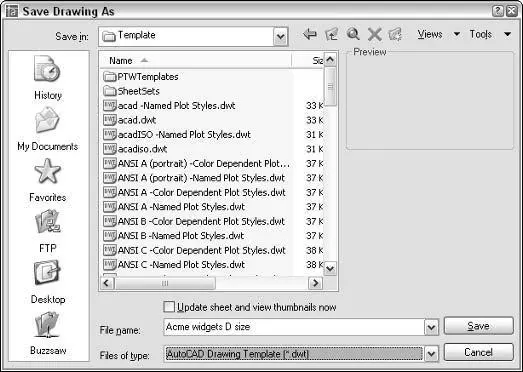
Figure 3-12:Saving a drawing as a template.
2. From the Save As Type pull-down menu, choose AutoCAD Drawing Template (*.dwt).
3. Navigate to the folder where you want to store the drawing.
AutoCAD 2005’s default folder for template drawings is called Template and is buried deep in the bowels of your Windows user profile. Save your templates there if you want them to appear in the AutoCAD’s Select Template list. You can save your templates in another folder, but if you want to use them later, you’ll have to navigate to that folder each time to use them. See the Technical Stuff paragraph after this procedure for additional suggestions.
4. Enter a name for the drawing template in the File Name text box.
5. Click the Save button to save your drawing template.
The drawing is saved as a template. A dialog box for the template description and units appears.
6. Enter the template’s measurement units (English or Metric).
Enter the key info now; you can’t do it later unless you save the template to a different name. Don’t bother filling in the Description field. AutoCAD doesn’t display it later in the Select Template dialog box.
7. Click OK to save the file.
8. To save your drawing as a regular drawing, choose File→Save As from the menu bar.
Читать дальшеИнтервал:
Закладка:
Похожие книги на «AutoCAD 2005 for Dummies»
Представляем Вашему вниманию похожие книги на «AutoCAD 2005 for Dummies» списком для выбора. Мы отобрали схожую по названию и смыслу литературу в надежде предоставить читателям больше вариантов отыскать новые, интересные, ещё непрочитанные произведения.


Обсуждение, отзывы о книге «AutoCAD 2005 for Dummies» и просто собственные мнения читателей. Оставьте ваши комментарии, напишите, что Вы думаете о произведении, его смысле или главных героях. Укажите что конкретно понравилось, а что нет, и почему Вы так считаете.