Mark Middlebrook - AutoCAD 2005 for Dummies
Здесь есть возможность читать онлайн «Mark Middlebrook - AutoCAD 2005 for Dummies» — ознакомительный отрывок электронной книги совершенно бесплатно, а после прочтения отрывка купить полную версию. В некоторых случаях можно слушать аудио, скачать через торрент в формате fb2 и присутствует краткое содержание. Город: Indianapolis, Год выпуска: 2004, ISBN: 2004, Издательство: Wiley Publishing, Inc, Жанр: Программы, на английском языке. Описание произведения, (предисловие) а так же отзывы посетителей доступны на портале библиотеки ЛибКат.

- Название:AutoCAD 2005 for Dummies
- Автор:
- Издательство:Wiley Publishing, Inc
- Жанр:
- Год:2004
- Город:Indianapolis
- ISBN:0-7645-7138-9
- Рейтинг книги:5 / 5. Голосов: 1
-
Избранное:Добавить в избранное
- Отзывы:
-
Ваша оценка:
AutoCAD 2005 for Dummies: краткое содержание, описание и аннотация
Предлагаем к чтению аннотацию, описание, краткое содержание или предисловие (зависит от того, что написал сам автор книги «AutoCAD 2005 for Dummies»). Если вы не нашли необходимую информацию о книге — напишите в комментариях, мы постараемся отыскать её.
AutoCAD is more than just another application program, it’s a complete environment for drafting and design. So if you’re new to AutoCAD, you need to know several things to get off to a good start — especially how to use the command line area and set up your drawing properly. These key techniques are described in this part of the book.
If you’ve used earlier versions of AutoCAD, you’ll be most interested in the high points of the new release, including some newer interface components. The lowdown on what’s new is here, too.
AutoCAD 2005 for Dummies — читать онлайн ознакомительный отрывок
Ниже представлен текст книги, разбитый по страницам. Система сохранения места последней прочитанной страницы, позволяет с удобством читать онлайн бесплатно книгу «AutoCAD 2005 for Dummies», без необходимости каждый раз заново искать на чём Вы остановились. Поставьте закладку, и сможете в любой момент перейти на страницу, на которой закончили чтение.
Интервал:
Закладка:
Conversely, if you know the sheet size that you’re going to use and the real-world size of what you’re going to draw, and you want to find out the largest plot scale you can use, you have to divide, not multiply. Divide the needed real-world drawing area dimensions (X and Y) by the sheet’s dimensions (X and Y). Take the larger number — either X or Y — and round up to the nearest real drawing scale factor (that is, one that’s commonly used in your industry). For example, suppose you want to draw a 60×40-foot or, 720×480-inch, floor plan and print it on 11×17-inch paper. You divide 720 by 17 and 480 by 11 to get 42.35 and 43.64, respectively. The larger number, 43.64, corresponds in this example to the short dimension of the house and the paper. The nearest larger common architectural drawing scale factor is 48 (corresponding to ¼”=1’–0”), which leaves a little room for the plotting margin and title block.
The Cheat Sheet at the front of this book includes two tables that list the available drawing areas for a range of sheet sizes and drawing scales. Use those tables to help you decide on an appropriate paper size and drawing scale, and revert to the calculation method for situations that the tables don’t cover. (If you don’t keep a favorite old calculator on your physical desktop, this may be a good time to put a shortcut to the Windows Calculator on your virtual one.)
 When you select a sheet size and drawing scale, always leave some extra room for the following two reasons:
□ Most plotters and printers can’t print all the way to the edge of the sheet — they require a small margin. For example, my trusty old Hewlett-Packard LaserJet III has a printable area of about 7.9×10.5 inches on an 8.5×11-inch ANSI A size (letter size) sheet. (You’ll find this information in the Plot dialog box, as described in Chapter 12.) If you’re a stickler for precision, you can use the printable area instead of the physical sheet area in the calculations described earlier in this section.
□ Most drawings require some annotations — text, grid bubbles, and so on — outside the objects you’re drawing, plus a title block surrounding the objects and annotations. If you don’t leave some room for the annotations and title block, you’ll end up having to cram things together too much or to change to a different sheet size. Either way, you’ll be slowed down later in the project when you can least afford it. Figure 3-3 shows an extreme example of selecting a sheet size that’s too small or, conversely, a drawing scale that’s too large. In this example, the building is too long for the sheet, and it overlaps the title block on both the right and left sides.
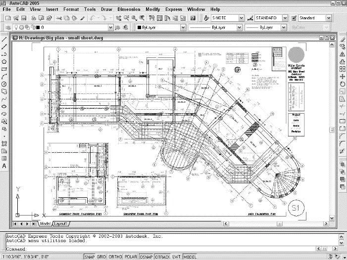
Figure 3-3:“This sheet size is too small,” said Goldilocks.
 Some industries deal with the “sheet-is-too-small/drawing-scale-is-too-large” problem by breaking drawings up onto multiple plotted sheets.
Don’t be afraid to start with paper. Experienced drafters often make a quick, throwaway pencil and paper sketch called a cartoon . A drawing cartoon usually includes a rectangle indicating the sheet of paper you intend to plot on, a sketch of the title block, and a very rough, schematic sketch of the thing you’re going to draw. It helps to scribble down the dimensions of the sheet, the main title block areas, and the major objects to be drawn. By sketching out a cartoon, you’ll often catch scale or paper size problems before you set up a drawing, when repairs only take a few minutes, not after you’ve created the drawing, when fixing the problem can take hours.
The next decision to make is what kind of border your drawing deserves. The options include a full-blown title block, a simple rectangle, or nothing at all around your drawing. If you need a title block, do you have one, can you borrow an existing one, or will you need to draw one from scratch? Although you can draw title block geometry in an individual drawing, you’ll save time by reusing the same title block for multiple drawings. Your company may already have a standard title block drawing ready to use, or someone else who’s working on your project may have created one for the project.
The right way to draw a title block is in a separate DWG file at its normal plotted size (for example, 36 inches long by 24 inches high for an architectural D size title block). You then insert or xref the title block drawing into each sheet drawing. Chapter 13 describes how to insert and xref separate DWG files.
As Chapter 2 describes, AutoCAD includes a slew of system variables that control the way your drawing and the AutoCAD program work. Much of the drawing setup process involves setting system variables based on the drawing scale, sheet size, and other desired properties of the drawing. You can set some system variables in AutoCAD dialog boxes, but a few require that you type at the command line. Table 3-3 shows the settings that you most commonly need to change — or at least check — during drawing setup, along with the names of the corresponding system variables. Later in the chapter, in the section “The Main Course: Model Space,” I show you the procedure for changing these settings.
Table 3-3 System Variables for Drawing Setup
| Setting | Dialog Box | System Variables |
|---|---|---|
| Linear units and precision | Drawing Units | LUNITS, LUPREC |
| Angular units and precision | Drawing Units | AUNITS, AUPREC |
| Grid spacing and visibility | Drafting Settings | GRIDUNIT, GRIDMODE |
| Snap spacing and on/off | Drafting Settings | SNAPUNIT, SNAPMODE |
| Drawing limits | None (use command line) | LIMMIN, LIMMAX |
| Linetype scale | Linetype Manager | LTSCALE, PSLTSCALE |
| Dimension scale | Dimension Style Manager | DIMSCALE |
Getting Creative with Templates
When you start AutoCAD 2004 with its desktop shortcut or from the Windows Start menu, AutoCAD creates a new, blank drawing based on the default template drawing (Acad.dwt). When you explicitly create a new drawing from within AutoCAD, the Select Template dialog box, shown in Figure 3-4, appears by default so that you can choose a template on which to base your new drawing.
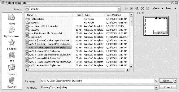
Figure 3-4:A plateful of templates to contemplate.
A template is simply a drawing whose name ends in the letters DWT, which you use as the starting point for another drawing. When you create a new drawing from a template, AutoCAD makes a copy of the template file and opens the copy in a new drawing editor window. The first time you save the file, you’re prompted for a new filename to save to; the original template file stays unchanged.
You may be familiar with the Microsoft Word or Excel template documents, and AutoCAD template drawings work pretty much the same way — because Autodesk stole the idea from them! (Encouraged, of course, by Microsoft.)
Читать дальшеИнтервал:
Закладка:
Похожие книги на «AutoCAD 2005 for Dummies»
Представляем Вашему вниманию похожие книги на «AutoCAD 2005 for Dummies» списком для выбора. Мы отобрали схожую по названию и смыслу литературу в надежде предоставить читателям больше вариантов отыскать новые, интересные, ещё непрочитанные произведения.


Обсуждение, отзывы о книге «AutoCAD 2005 for Dummies» и просто собственные мнения читателей. Оставьте ваши комментарии, напишите, что Вы думаете о произведении, его смысле или главных героях. Укажите что конкретно понравилось, а что нет, и почему Вы так считаете.