Ibrahim Dogan - Advanced PIC Microcontroller Projects in C
Здесь есть возможность читать онлайн «Ibrahim Dogan - Advanced PIC Microcontroller Projects in C» весь текст электронной книги совершенно бесплатно (целиком полную версию без сокращений). В некоторых случаях можно слушать аудио, скачать через торрент в формате fb2 и присутствует краткое содержание. Город: Burlington, Год выпуска: 2008, ISBN: 2008, Издательство: Elsevier Ltd, Жанр: Программирование, Компьютерное железо, на английском языке. Описание произведения, (предисловие) а так же отзывы посетителей доступны на портале библиотеки ЛибКат.

- Название:Advanced PIC Microcontroller Projects in C
- Автор:
- Издательство:Elsevier Ltd
- Жанр:
- Год:2008
- Город:Burlington
- ISBN:978-0-7506-8611-2
- Рейтинг книги:5 / 5. Голосов: 1
-
Избранное:Добавить в избранное
- Отзывы:
-
Ваша оценка:
Advanced PIC Microcontroller Projects in C: краткое содержание, описание и аннотация
Предлагаем к чтению аннотацию, описание, краткое содержание или предисловие (зависит от того, что написал сам автор книги «Advanced PIC Microcontroller Projects in C»). Если вы не нашли необходимую информацию о книге — напишите в комментариях, мы постараемся отыскать её.
• Features 20 complete, tried and test projects
• Includes a CD-ROM of all the programs, hex listings, diagrams, and data sheets
Advanced PIC Microcontroller Projects in C — читать онлайн бесплатно полную книгу (весь текст) целиком
Ниже представлен текст книги, разбитый по страницам. Система сохранения места последней прочитанной страницы, позволяет с удобством читать онлайн бесплатно книгу «Advanced PIC Microcontroller Projects in C», без необходимости каждый раз заново искать на чём Вы остановились. Поставьте закладку, и сможете в любой момент перейти на страницу, на которой закончили чтение.
Интервал:
Закладка:
// between 1 and Lim
//
unsigned char Number(int Lim, int Y) {
unsigned char Result;
static unsigned int Y;
Y = (Y * 32719 + 3) % 32749;
Result = ((Y % Lim) + 1);
return Result;
}
//
// Start of MAIN program
//
void main() {
unsigned char J,Pattern,Seed = 1;
unsigned char DICE[] = {0,0x08,0x22,0x2A,0x55,0x5D,0x77};
TRISC = 0; // PORTC are outputs
TRISD = 0; // PORTD are outputs
TRISB = 1; // RB0 input
PORTC = 0; // Turn OFF all LEDs
PORTD = 0; // Turn OFF all LEDs
for(;;) // Endless loop
{
if (Switch == Pressed) // Is switch pressed ?
{
J = Number(6,seed); // Generate first dice number
Pattern = DICE[J]; // Get LED pattern
PORTC = Pattern; // Turn on LEDs for first dice
J = Number(6,seed); // Generate second dice number
Pattern = DICE[J]; // Get LED pattern
PORTD = Pattern; // Turn on LEDs for second dice
Delay_ms(3000); // Delay 3 seconds
PORTC = 0; // Turn OFF all LEDs
PORTD = 0; // Turn OFF all LEDS
}
}
}

Figure 6.15: Program listing
PROJECT 6.4 — Two-Dice Project Using Fewer I/O Pins
Project Description
This project is similar to Project 3, but here LEDs are shared, which uses fewer input/output pins.
The LEDs in Table 6.1 can be grouped as shown in Table 6.3. Looking at this table we can say that:
• D4 can appear on its own
• D2 and D6 are always together
• D1 and D3 are always together
• D5 and D7 are always together
Table 6.3: Grouping the LEDs
| Required number | LEDs to be turned on |
|---|---|
| 1 | D4 |
| 2 | D2 D6 |
| 3 | D2 D6 D4 |
| 4 | D1 D3 D5 D7 |
| 5 | D1 D3 D5 D7 D4 |
| 6 | D2 D6 D1 D3 D5 D7 |
Thus, we can drive D4 on its own and then drive the D2, D6 pair together in series, the D1, D3 pair together in series, and also the D5, D7 pair together in series. (Actually, we could share D1, D3, D5, D7 but this would require 8 volts to drive if the LEDs are connected in series. Connecting them in parallel would call for even more current, and a driver IC would be required.) Altogether, four lines are needed to drive the seven LEDs of each dice. Thus, a pair of dice can easily be driven from an 8-bit output port.
Project Hardware
The circuit diagram of the project is shown in Figure 6.16. PORTC of a PIC18F452 microcontroller is used to drive the LEDs as follows:
• RC0 drives D2,D6 of the first dice
• RC1 drives D1,D3 of the first dice
• RC2 drives D5,D7 of the first dice
• RC3 drives D4 of the first dice
• RC4 drives D2,D6 of the second dice
• RC5 drives D1,D3 of the second dice
• RC6 drives D5,D7 of the second dice
• RC7 drives D4 of the second dice
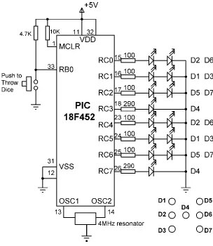
Figure 6.16: Circuit diagram of the project
Since two LEDs are being driven on some outputs, we can calculate the required value of the current limiting resistors. Assuming that the voltage drop across each LED is 2V, the current through the LED is 10mA, and the output high voltage of the microcontroller is 4.85V, the required resistors are:
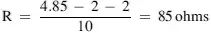
We will choose 100-ohm resistors.
We now need to find the relationship between the dice numbers and the bit pattern to be sent to the LEDs for each dice. Table 6.4 shows the relationship between the first dice numbers and the bit pattern to be sent to port pins RC0–RC3. Similarly, Table 6.5 shows the relationship between the second dice numbers and the bit pattern to be sent to port pins RC4–RC7.
Table 6.4: First dice bit patterns
| Dice number | RC3 | RC2 | RC1 | RC0 | Hex value |
|---|---|---|---|---|---|
| 1 | 1 | 0 | 0 | 0 | 8 |
| 2 | 0 | 0 | 0 | 1 | 1 |
| 3 | 1 | 0 | 0 | 1 | 9 |
| 4 | 0 | 1 | 1 | 0 | 6 |
| 5 | 1 | 1 | 1 | 0 | E |
| 6 | 0 | 1 | 1 | 1 | 7 |
Table 6.5: Second dice bit patterns
| Dice number | RC3 | RC2 | RC1 | RC0 | Hex value |
|---|---|---|---|---|---|
| 1 | 1 | 0 | 0 | 0 | 8 |
| 2 | 0 | 0 | 0 | 1 | 1 |
| 3 | 1 | 0 | 0 | 1 | 9 |
| 4 | 0 | 1 | 1 | 0 | 6 |
| 5 | 1 | 1 | 1 | 0 | E |
| 6 | 0 | 1 | 1 | 1 | 7 |
We can now find the 8-bit number to be sent to PORTC to display both dice numbers as follows:
• Get the first number from the number generator, call this P
• Index the DICE table to find the bit pattern for low nibble (i.e., L = DICE[P])
• Get the second number from the number generator, call this P
• Index the DICE table to find the bit pattern for high nibble (i.e., U = DICE[P])
• Multiply high nibble by 16 and add low nibble to find the number to be sent to PORTC (i.e., R = 16*U + L), where R is the 8-bit number to be sent to PORTC to display both dice values.
Project PDL
The operation of this project is very similar to that of Project 2. Figure 6.17 shows the PDL of the project. At the beginning of the program the PORTC pins are configured as outputs, and bit 0 of PORTB (RB0) is configured as input. The program then executes in a loop continuously and checks the state of the push-button switch. When the switch is pressed, two pseudorandom numbers between 1 and 6 are generated, and the bit pattern to be sent to PORTC is found by the method just described. This bit pattern is then sent to PORTC to display both dice numbers at the same time. The display shows the dice numbers for 3 seconds, and then all the LEDs turn OFF to indicate that the system is waiting for the push-button to be pressed again to display the next set of numbers.
START
Create DICE table
Configure PORTC as outputs
Configure RB0 as input
DO FOREVER
IF button pressed THEN
Get a random number between 1 and 6
Find low nibble bit pattern
Get second random number between 1 and 6
High high nibble bit pattern
Calculate data to be sent to PORTC
Wait 3 seconds
Turn OFF all LEDs
ENDIF
ENDDO
END
Интервал:
Закладка:
Похожие книги на «Advanced PIC Microcontroller Projects in C»
Представляем Вашему вниманию похожие книги на «Advanced PIC Microcontroller Projects in C» списком для выбора. Мы отобрали схожую по названию и смыслу литературу в надежде предоставить читателям больше вариантов отыскать новые, интересные, ещё непрочитанные произведения.


Обсуждение, отзывы о книге «Advanced PIC Microcontroller Projects in C» и просто собственные мнения читателей. Оставьте ваши комментарии, напишите, что Вы думаете о произведении, его смысле или главных героях. Укажите что конкретно понравилось, а что нет, и почему Вы так считаете.