Ibrahim Dogan - Advanced PIC Microcontroller Projects in C
Здесь есть возможность читать онлайн «Ibrahim Dogan - Advanced PIC Microcontroller Projects in C» весь текст электронной книги совершенно бесплатно (целиком полную версию без сокращений). В некоторых случаях можно слушать аудио, скачать через торрент в формате fb2 и присутствует краткое содержание. Город: Burlington, Год выпуска: 2008, ISBN: 2008, Издательство: Elsevier Ltd, Жанр: Программирование, Компьютерное железо, на английском языке. Описание произведения, (предисловие) а так же отзывы посетителей доступны на портале библиотеки ЛибКат.

- Название:Advanced PIC Microcontroller Projects in C
- Автор:
- Издательство:Elsevier Ltd
- Жанр:
- Год:2008
- Город:Burlington
- ISBN:978-0-7506-8611-2
- Рейтинг книги:5 / 5. Голосов: 1
-
Избранное:Добавить в избранное
- Отзывы:
-
Ваша оценка:
Advanced PIC Microcontroller Projects in C: краткое содержание, описание и аннотация
Предлагаем к чтению аннотацию, описание, краткое содержание или предисловие (зависит от того, что написал сам автор книги «Advanced PIC Microcontroller Projects in C»). Если вы не нашли необходимую информацию о книге — напишите в комментариях, мы постараемся отыскать её.
• Features 20 complete, tried and test projects
• Includes a CD-ROM of all the programs, hex listings, diagrams, and data sheets
Advanced PIC Microcontroller Projects in C — читать онлайн бесплатно полную книгу (весь текст) целиком
Ниже представлен текст книги, разбитый по страницам. Система сохранения места последней прочитанной страницы, позволяет с удобством читать онлайн бесплатно книгу «Advanced PIC Microcontroller Projects in C», без необходимости каждый раз заново искать на чём Вы остановились. Поставьте закладку, и сможете в любой момент перейти на страницу, на которой закончили чтение.
Интервал:
Закладка:
/*****************************************************************************
7-SEGMENT DISPLAY
=================
In this project a common anode 7-segment LED display is connected to PORTC
of a PIC18F452 microcontroller and the microcontroller is operated from a 4MHz
resonator. The program displays numbers 0 to 9 on the display with a one
second delay between each output.
Author: Dogan Ibrahim
Date: July 2007
File: SEVEN1.C
******************************************************************************/
void main() {
unsigned char Pattern, Cnt = 0;
unsigned char SEGMENT[] = {0x3F,0x06,0x5B,0x4F,0x66,0x6D,
0x7D,0x07,0x7F,0x6F};
TRISC = 0; // PORTC are outputs
for(;;) // Endless loop
{
Pattern = SEGMENT[Cnt]; // Number to send to PORTC
Pattern = ~Pattern; // Invert bit pattern
PORTC = Pattern; // Send to PORTC
Cnt++;
if (Cnt == 10) Cnt = 0; // Cnt is between 0 and 9
Delay_ms(1000); // 1 second delay
}
}

Figure 6.27: Program listing
Modified Program
Note that the program can be made more readable if we create a function to display the required number and then call this function from the main program. Figure 6.28 shows the modified program (called SEVEN2.C). A function called Display is created with an argument called no . The function gets the bit pattern from local array SEGMENT indexed by no , inverts it, and then returns the resulting bit pattern to the calling program.
/*****************************************************************************
7-SEGMENT DISPLAY
=================
In this project a common anode 7-segment LED display is connected to
PORTC of a PIC18F452 microcontroller and the microcontroller is
operated from a 4MHz resonator. The program displays numbers 0 to 9 on
the display with a one second delay between each output.
In this version of the program a function called Display is used to display
the number.
Author: Dogan Ibrahim
Date: July 2007
File: SEVEN2.C
*******************************************************************************/
//
// This function displays a number on the 7-segment LED.
// The number is passed in the argument list of the function.
//
unsigned char Display(unsigned char no) {
unsigned char Pattern;
unsigned char SEGMENT[] = {0x3F,0x06,0x5B,0x4F,0x66,0x6D,
0x7D,0x07,0x7F,0x6F};
Pattern = SEGMENT[no];
Pattern = ~Pattern; // Pattern to return
return (Pattern);
}
//
// Start of MAIN Program
//
void main() {
unsigned char Cnt = 0;
TRISC = 0; // PORTC are outputs
for(;;) // Endless loop
{
PORTC = Display(Cnt); // Send to PORTC
Cnt++;
if (Cnt == 10) Cnt = 0; // Cnt is between 0 and 9
Delay_ms(1000); // 1 second delay
}
}
Figure 6.28: Modified program listing
PROJECT 6.6 — Two-Digit Multiplexed 7-Segment LED
Project Description
This project is similar to Project 6.5, but here multiplexed two digits are used instead of just one digit and a fixed number. In this project the number 25 is displayed. In multiplexed LED applications (see Figure 6.29) the LED segments of all the digits are tied together and the common pins of each digit are turned ON separately by the microcontroller. When each digit is displayed only for several milliseconds, the eye cannot tell that the digits are not ON all the time. This way we can multiplex any number of 7-segment displays together. For example, to display the number 53, we have to send 5 to the first digit and enable its common pin. After a few milliseconds, number 3 is sent to the second digit and the common point of the second digit is enabled. When this process is repeated continuously, it appears to the user that both displays are ON continuously.
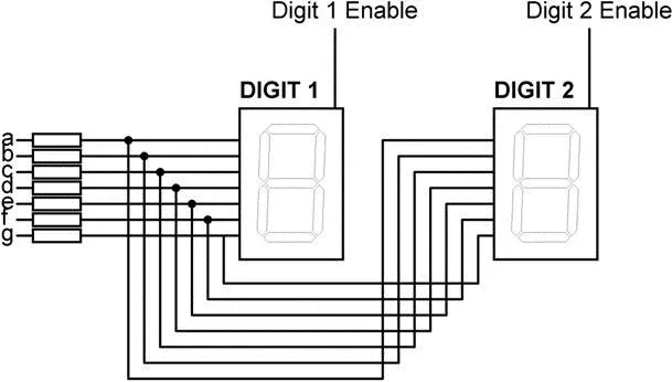
Figure 6.29: Two multiplexed 7-segment displays
Some manufacturers provide multiplexed multidigit displays, such as 2-, 4-, or 8-digit multiplexed displays, in single packages. The display used in this project is the DC5611EWA, which is a red 0.56-inch common-cathode two-digit display having 18 pins and the pin configuration as shown in Table 6.9. This display can be controlled from the microcontroller as follows:
• Send the segment bit pattern for digit 1 to segments a to g
• Enable digit 1
• Wait for a few milliseconds
• Disable digit 1
• Send the segment bit pattern for digit 2 to segments a to g
• Enable digit 2
• Wait for a few milliseconds
• Disable digit 2
• Repeat these steps continuously
Table 6.9: Pin configuration of DC56-11EWA dual display
| Pin no. | Segment |
|---|---|
| 1,5 | E |
| 2,6 | D |
| 3,8 | C |
| 14 | Digit 1 enable |
| 17,7 | G |
| 15,10 | B |
| 16,11 | A |
| 18,12 | F |
| 13 | Digit 2 enable |
| 4 | Decimal point 1 |
| 9 | Decimal point 2 |
The segment configuration of the DC56-11EWA display is shown in Figure 6.30. In a multiplexed display application the segment pins of corresponding segments are connected together. For example, pins 11 and 16 are connected as the common a segment, pins 15 and 10 are connected as the common b segment, and so on.
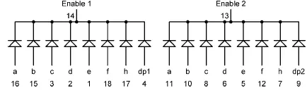
Figure 6.30: DC56-11EWA display segment configuration
Project Hardware
The block diagram of this project is shown in Figure 6.31. The circuit diagram is given in Figure 6.32. The segments of the display are connected to PORTC of a PIC18F452-type microcontroller, operated with a 4MHz resonator. Current limiting resistors are used on each segment of the display. Each digit is enabled using a BC108-type transistor switch connected to port pins RB0 and RB1 of the microcontroller. A segment is turned on when a logic 1 is applied to the base of the corresponding segment transistor.
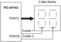
Figure 6.31: Block diagram of the project
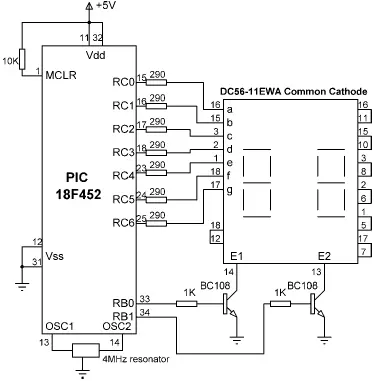
Figure 6.32: Circuit diagram of the project
Читать дальшеИнтервал:
Закладка:
Похожие книги на «Advanced PIC Microcontroller Projects in C»
Представляем Вашему вниманию похожие книги на «Advanced PIC Microcontroller Projects in C» списком для выбора. Мы отобрали схожую по названию и смыслу литературу в надежде предоставить читателям больше вариантов отыскать новые, интересные, ещё непрочитанные произведения.


Обсуждение, отзывы о книге «Advanced PIC Microcontroller Projects in C» и просто собственные мнения читателей. Оставьте ваши комментарии, напишите, что Вы думаете о произведении, его смысле или главных героях. Укажите что конкретно понравилось, а что нет, и почему Вы так считаете.