Ibrahim Dogan - Advanced PIC Microcontroller Projects in C
Здесь есть возможность читать онлайн «Ibrahim Dogan - Advanced PIC Microcontroller Projects in C» весь текст электронной книги совершенно бесплатно (целиком полную версию без сокращений). В некоторых случаях можно слушать аудио, скачать через торрент в формате fb2 и присутствует краткое содержание. Город: Burlington, Год выпуска: 2008, ISBN: 2008, Издательство: Elsevier Ltd, Жанр: Программирование, Компьютерное железо, на английском языке. Описание произведения, (предисловие) а так же отзывы посетителей доступны на портале библиотеки ЛибКат.

- Название:Advanced PIC Microcontroller Projects in C
- Автор:
- Издательство:Elsevier Ltd
- Жанр:
- Год:2008
- Город:Burlington
- ISBN:978-0-7506-8611-2
- Рейтинг книги:5 / 5. Голосов: 1
-
Избранное:Добавить в избранное
- Отзывы:
-
Ваша оценка:
Advanced PIC Microcontroller Projects in C: краткое содержание, описание и аннотация
Предлагаем к чтению аннотацию, описание, краткое содержание или предисловие (зависит от того, что написал сам автор книги «Advanced PIC Microcontroller Projects in C»). Если вы не нашли необходимую информацию о книге — напишите в комментариях, мы постараемся отыскать её.
• Features 20 complete, tried and test projects
• Includes a CD-ROM of all the programs, hex listings, diagrams, and data sheets
Advanced PIC Microcontroller Projects in C — читать онлайн бесплатно полную книгу (весь текст) целиком
Ниже представлен текст книги, разбитый по страницам. Система сохранения места последней прочитанной страницы, позволяет с удобством читать онлайн бесплатно книгу «Advanced PIC Microcontroller Projects in C», без необходимости каждый раз заново искать на чём Вы остановились. Поставьте закладку, и сможете в любой момент перейти на страницу, на которой закончили чтение.
Интервал:
Закладка:
Project PDL
At the beginning of the program PORTB and PORTC pins are configured as outputs. The program then enters an endless loop where first of all the Most Significant Digit (MSD) of the number is calculated, function Display is called to find the bit pattern and then sent to the display, and digit 1 is enabled. Then, after a small delay, digit 1 is disabled, the Least Significant Digit (LSD) of the number is calculated, function Display is called to find the bit pattern and then sent to the display, and digit 2 is enabled. Then again after a small delay, digit 2 is disabled, and this process repeats indefinitely. Figure 6.33 shows the PDL of the project.
START
Create SEGMENT table
Configure PORTB as outputs
Configure PORTC as outputs
Initialize CNT to 25
DO FOREVER
Find MSD digit
Get bit pattern from SEGMENT
Enable digit 1
Wait for a while
Disable digit 1
Find LSD digit
Get bit pattern from SEGMENT
Enable digit 2
Wait for a while
Disable digit 2
ENDDO
END

Figure 6.33: PDL of the project
Project Program
The program is named SEVEN3.C, and the listing is shown in Figure 6.34. DIGIT1 and DIGIT2 are defined as equal to bit 0 and bit 1 of PORTB respectively. The value to be displayed (the number 25) is stored in variable Cnt . An endless loop is formed using a for statement. Inside the loop, the MSD of the number is calculated by dividing the number by 10. Function Display is then called to find the bit pattern to send to PORTC. Then digit 1 is enabled by setting DIGIT1 = 1 and the program waits for 10ms. After this, digit 1 is disabled and the LSD of the number is calculated using the mod operator (“%”) and sent to PORTC. At the same time, digit 2 is enabled by setting DIGIT2 = 1 and the program waits for 10ms. After this time digit 2 is disabled, and the program repeats forever.
/*********************************************************************
Dual 7-SEGMENT DISPLAY
======================
In this project two common cathode 7-segment LED displays are connected to
PORTC of a PIC18F452 microcontroller and the microcontroller is operated
from a 4MHz resonator. Digit 1 (left digit) enable pin is connected to port
pin RB0 and digit 2 (right digit) enable pin is connected to port pin RB1
of the microcontroller. The program displays number 25 on the displays.
Author: Dogan Ibrahim
Date: July 2007
File: SEVEN3.C
***********************************************************************/
#define DIGIT1 PORTB.F0
#define DIGIT2 PORTB.F1
//
// This function finds the bit pattern to be sent to the port to display a
// number on the 7-segment LED. The number is passed in the argument list
// of the function.
//
unsigned char Display(unsigned char no) {
unsigned char Pattern;
unsigned char SEGMENT[] = {0x3F,0x06,0x5B,0x4F,0x66,0x6D,
0x7D,0x07,0x7F,0x6F};
Pattern = SEGMENT[no]; // Pattern to return
return (Pattern);
}
//
// Start of MAIN Program
//
void main() {
unsigned char Msd, Lsd, Cnt = 25;
TRISC = 0; // PORTC are outputs
TRISB = 0; // RB0, RB1 are outputs
DIGIT1 = 0; // Disable digit 1
DIGIT2 = 0; // Disable digit 2
for(;;) // Endless loop
{
Msd = Cnt / 10; // MSD digit
PORTC = Display(Msd); // Send to PORTC
DIGIT1 = 1; // Enable digit 1
Delay_Ms(10); // Wait a while
DIGIT1 = 0; // Disable digit 1
Lsd = Cnt % 10; // LSD digit
PORTC = Display(Lsd); // Send to PORTC
DIGIT2 = 1; // Enable digit 2
Delay_Ms(10); // Wait a while
DIGIT2 = 0; // Disable digit 2
}
}
Figure 6.34: Program listing
PROJECT 6.7 — Two-Digit Multiplexed 7-Segment LED Counter with Timer Interrupt
Project Description
This project is similar to Project 6 but here the microcontroller’s timer interrupt is used to refresh the displays. In Project 6 the microcontroller was busy updating the displays every 10ms and could not perform any other tasks. For example, the program given in Project 6 cannot be used to make a counter with a one-second delay between counts, as the displays cannot be updated while the program waits for one second.
In this project a counter is designed to count from 0 to 99, and the display is refreshed every 5ms inside the timer interrupt service routine. The main program can then perform other tasks, in this example incrementing the count and waiting for one second between counts.
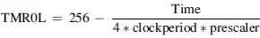
In this project Timer 0 is operated in 8-bit mode. The time for an interrupt is given by:
Time = (4 × clock period) × Prescaler × (256 – TMR0L)
where Prescaler is the selected prescaler value, and TMR0L is the value loaded into timer register TMR0L to generate timer interrupts every Time period.
In our application the clock frequency is 4MHz, that is, clock period = 0.25μs, and Time = 5ms. Selecting a prescaler value of 32, the number to be loaded into TMR0L can be calculated as follows:
or
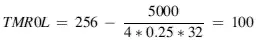
Thus, TMR0L should be loaded with 100. The value to be loaded into TMR0 control register T0CON can then be found as:
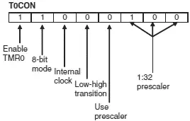
Thus, T0CON register should be loaded with hexadecimal 0xC4. The next register to be configured is the interrupt control register INTCON, where we will disable priority based interrupts and enable the global interrupts and TMR0 interrupts:
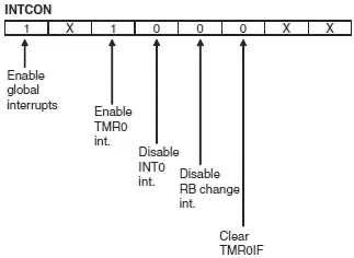
Taking the don’t-care entries (X) as 0, the hexadecimal value to be loaded into register INTCON is 0xA0.
When an interrupt occurs, the program automatically jumps to the interrupt service routine. Inside this routine we have to reload register TMR0L, reenable the TMR0 interrupts, and clear the TMR0 interrupt flag bit. Setting INTCON register to 0x20 reenables the TMR0 interrupts and at the same time clears the TMR0 interrupt flag.
The operations to be performed can thus be summarized as follows:
Читать дальшеИнтервал:
Закладка:
Похожие книги на «Advanced PIC Microcontroller Projects in C»
Представляем Вашему вниманию похожие книги на «Advanced PIC Microcontroller Projects in C» списком для выбора. Мы отобрали схожую по названию и смыслу литературу в надежде предоставить читателям больше вариантов отыскать новые, интересные, ещё непрочитанные произведения.


Обсуждение, отзывы о книге «Advanced PIC Microcontroller Projects in C» и просто собственные мнения читателей. Оставьте ваши комментарии, напишите, что Вы думаете о произведении, его смысле или главных героях. Укажите что конкретно понравилось, а что нет, и почему Вы так считаете.