Ibrahim Dogan - Advanced PIC Microcontroller Projects in C
Здесь есть возможность читать онлайн «Ibrahim Dogan - Advanced PIC Microcontroller Projects in C» весь текст электронной книги совершенно бесплатно (целиком полную версию без сокращений). В некоторых случаях можно слушать аудио, скачать через торрент в формате fb2 и присутствует краткое содержание. Город: Burlington, Год выпуска: 2008, ISBN: 2008, Издательство: Elsevier Ltd, Жанр: Программирование, Компьютерное железо, на английском языке. Описание произведения, (предисловие) а так же отзывы посетителей доступны на портале библиотеки ЛибКат.

- Название:Advanced PIC Microcontroller Projects in C
- Автор:
- Издательство:Elsevier Ltd
- Жанр:
- Год:2008
- Город:Burlington
- ISBN:978-0-7506-8611-2
- Рейтинг книги:5 / 5. Голосов: 1
-
Избранное:Добавить в избранное
- Отзывы:
-
Ваша оценка:
Advanced PIC Microcontroller Projects in C: краткое содержание, описание и аннотация
Предлагаем к чтению аннотацию, описание, краткое содержание или предисловие (зависит от того, что написал сам автор книги «Advanced PIC Microcontroller Projects in C»). Если вы не нашли необходимую информацию о книге — напишите в комментариях, мы постараемся отыскать её.
• Features 20 complete, tried and test projects
• Includes a CD-ROM of all the programs, hex listings, diagrams, and data sheets
Advanced PIC Microcontroller Projects in C — читать онлайн бесплатно полную книгу (весь текст) целиком
Ниже представлен текст книги, разбитый по страницам. Система сохранения места последней прочитанной страницы, позволяет с удобством читать онлайн бесплатно книгу «Advanced PIC Microcontroller Projects in C», без необходимости каждый раз заново искать на чём Вы остановились. Поставьте закладку, и сможете в любой момент перейти на страницу, на которой закончили чтение.
Интервал:
Закладка:
TRISC = 0; // PORTC are outputs
TRISB = 1; // RB0 input
PORTC = 0; // Turn OFF all LEDs
for(;;) // Endless loop
{
if (Switch == Pressed) // Is switch pressed ?
{
Pattern = DICE[J]; // Number to send to PORTC
PORTC = Pattern; // send to PORTC
Delay_ms(3000); // 3 seconds delay
PORTC = 0; // Clear PORTC
}
J++; // Increment J
if (J == 37) J = 1; // If J = 37, reset to 1
}
}

Figure 6.19: Modified program
PROJECT 6.5 — 7-Segment LED Counter
Project Description
This project describes the design of a 7-segment LED-based counter which counts from 0 to 9 continuously with a one-second delay between counts. The project shows how a 7-segment LED can be interfaced and used in a PIC microcontroller project.
7-segment displays are used frequently in electronic circuits to show numeric or alphanumeric values. As shown in Figure 6.20, a 7-segment display consists basically of 7 LEDs connected such that the numbers from 0 to 9 and some letters can be displayed. Segments are identified by the letters from a to g, and Figure 6.21 shows the segment names of a typical 7-segment display.
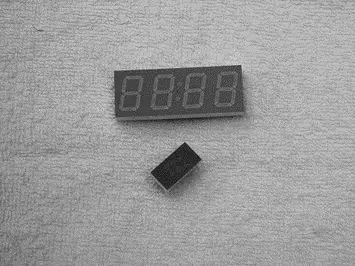
Figure 6.20: Some 7-segment displays
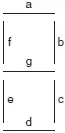
Figure 6.21: Segment names of a 7-segment display
Figure 6.22 shows how the numbers from 0 to 9 are obtained by turning ON different segments of the display.
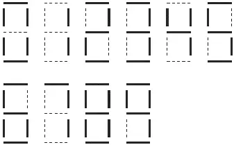
Figure 6.22: Displaying numbers 0 to 9
7-segment displays are available in two different configurations: common cathode and common anode. As shown in Figure 6.23, in common cathode configuration, all the cathodes of all segment LEDs are connected together to the ground. The segments are turned ON by applying a logic 1 to the required segment LED via current limiting resistors. In common cathode configuration the 7-segment LED is connected to the microcontroller in current sourcing mode.
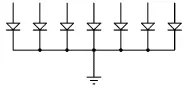
Figure 6.23: Common cathode configuration
In common anode configuration, the anode terminals of all the LEDs are connected together as shown in Figure 6.24. This common point is then normally connected to the supply voltage. A segment is turned ON by connecting its cathode terminal to logic 0 via a current limiting resistor. In common anode configuration the 7-segment LED is connected to the microcontroller in current sinking mode.
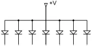
Figure 6.24: Common anode configuration
In this project, a Kingbright SA52-11 red common anode 7-segment display is used. This is a 13mm (0.52 inch) display with ten pins that includes a segment LED for the decimal point. Table 6.7 shows the pin configuration of this display.
Table 6.7: SA52-11 pin configuration
| Pin | number Segment |
|---|---|
| 1 | e |
| 2 | d |
| 3 | common anode |
| 4 | c |
| 5 | decimal point |
| 6 | b |
| 7 | a |
| 8 | common anode |
| 9 | f |
| 10 | g |
Project Hardware
The circuit diagram of the project is shown in Figure 6.25. A PIC18F452 type microcontroller is used with a 4MHz resonator. Segments a to g of the display are connected to PORTC of the microcontroller through 290-ohm current limiting resistors. Before driving the display, we have to know the relationship between the numbers to be displayed and the corresponding segments to be turned ON, and this is shown in Table 6.8. For example, to display number 3 we have to send the hexadecimal number 0x4F to PORTC, which turns ON segments a,b,c,d, and g. Similarly, to display number 9 we have to send the hexadecimal number 0x6F to PORTC which turns ON segments a,b,c,d,f, and g.
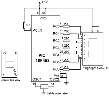
Figure 6.25: Circuit diagram of the project
Table 6.8: Displayed number and data sent to PORTC
| Number | x | g | f | e | d | c | b | a | PORTC Data |
|---|---|---|---|---|---|---|---|---|---|
| 0 | 0 | 0 | 1 | 1 | 1 | 1 | 1 | 1 | 0x3F |
| 1 | 0 | 0 | 0 | 0 | 0 | 1 | 1 | 0 | 0x06 |
| 2 | 0 | 1 | 0 | 1 | 1 | 0 | 1 | 1 | 0x5B |
| 3 | 0 | 1 | 0 | 0 | 1 | 1 | 1 | 1 | 0x4F |
| 4 | 0 | 1 | 1 | 0 | 0 | 1 | 1 | 0 | 0x66 |
| 5 | 0 | 1 | 1 | 0 | 1 | 1 | 0 | 1 | 0x6D |
| 6 | 0 | 1 | 1 | 1 | 1 | 1 | 0 | 1 | 0x7D |
| 7 | 0 | 0 | 0 | 0 | 0 | 1 | 1 | 1 | 0x07 |
| 8 | 0 | 1 | 1 | 1 | 1 | 1 | 1 | 1 | 0x7F |
| 9 | 0 | 1 | 1 | 0 | 1 | 1 | 1 | 1 | 0x6F |
x is not used, taken as 0.
Project PDL
The operation of the project is shown in Figure 6.26 with a PDL. At the beginning of the program an array called SEGMENT is declared and filled with the relationships between the numbers 0 and 9 and the data to be sent to PORTC. The PORTC pins are then configured as outputs, and a variable is initialized to 0. The program then enters an endless loop where the variable is incremented between 0 and 9 and the corresponding bit pattern to turn ON the appropriate segments is sent to PORTC continuously with a one-second delay between outputs.
START
Create SEGMENT table
Configure PORTC as outputs
Initialize CNT to 0
DO FOREVER
Get bit pattern from SEGMENT corresponding to CNT
Send this bit pattern to PORTC
Increment CNT between 0 and 9
Wait 1 second
ENDDO
END
Figure 6.26: PDL of the project
Project Program
The program is called SEVEN1.C and the listing is given in Figure 6.27. At the beginning of the program character variables Pattern and Cnt are declared, and Cnt is cleared to 0. Then Table 6.8 is implemented using array SEGMENT. After configuring the PORTC pins as outputs, the program enters an endless loop using a for statement. Inside the loop the bit pattern corresponding to the contents of Cnt is found and stored in variable Pattern . Because we are using a common anode display, a segment is turned ON when it is at logic 0 and thus the bit pattern is inverted before it is sent to PORTC. The value of Cnt is then incremented between 0 and 9, after which the program waits for a second before repeating the above sequence.
Читать дальшеИнтервал:
Закладка:
Похожие книги на «Advanced PIC Microcontroller Projects in C»
Представляем Вашему вниманию похожие книги на «Advanced PIC Microcontroller Projects in C» списком для выбора. Мы отобрали схожую по названию и смыслу литературу в надежде предоставить читателям больше вариантов отыскать новые, интересные, ещё непрочитанные произведения.


Обсуждение, отзывы о книге «Advanced PIC Microcontroller Projects in C» и просто собственные мнения читателей. Оставьте ваши комментарии, напишите, что Вы думаете о произведении, его смысле или главных героях. Укажите что конкретно понравилось, а что нет, и почему Вы так считаете.