Ibrahim Dogan - Advanced PIC Microcontroller Projects in C
Здесь есть возможность читать онлайн «Ibrahim Dogan - Advanced PIC Microcontroller Projects in C» весь текст электронной книги совершенно бесплатно (целиком полную версию без сокращений). В некоторых случаях можно слушать аудио, скачать через торрент в формате fb2 и присутствует краткое содержание. Город: Burlington, Год выпуска: 2008, ISBN: 2008, Издательство: Elsevier Ltd, Жанр: Программирование, Компьютерное железо, на английском языке. Описание произведения, (предисловие) а так же отзывы посетителей доступны на портале библиотеки ЛибКат.

- Название:Advanced PIC Microcontroller Projects in C
- Автор:
- Издательство:Elsevier Ltd
- Жанр:
- Год:2008
- Город:Burlington
- ISBN:978-0-7506-8611-2
- Рейтинг книги:5 / 5. Голосов: 1
-
Избранное:Добавить в избранное
- Отзывы:
-
Ваша оценка:
Advanced PIC Microcontroller Projects in C: краткое содержание, описание и аннотация
Предлагаем к чтению аннотацию, описание, краткое содержание или предисловие (зависит от того, что написал сам автор книги «Advanced PIC Microcontroller Projects in C»). Если вы не нашли необходимую информацию о книге — напишите в комментариях, мы постараемся отыскать её.
• Features 20 complete, tried and test projects
• Includes a CD-ROM of all the programs, hex listings, diagrams, and data sheets
Advanced PIC Microcontroller Projects in C — читать онлайн бесплатно полную книгу (весь текст) целиком
Ниже представлен текст книги, разбитый по страницам. Система сохранения места последней прочитанной страницы, позволяет с удобством читать онлайн бесплатно книгу «Advanced PIC Microcontroller Projects in C», без необходимости каждый раз заново искать на чём Вы остановились. Поставьте закладку, и сможете в любой момент перейти на страницу, на которой закончили чтение.
Интервал:
Закладка:
Connecting the LCD
The mikroC compiler assumes by default that the LCD is connected to the microcontroller as follows:
LCD Microcontroller port
D7 Bit 7 of the port
D6 Bit 6 of the port
D5 Bit 5 of the port
D4 Bit 4 of the port
E Bit 3 of the port
RS Bit 2 of the port
where port is the port name specified using the Lcd_Init statement.
For example, we can use the statement Lcd_Init(&PORTB) if the LCD is connected to PORTB with the default connection.
It is also possible to connect the LCD differently, using the command Lcd_Config to define the connection.
Project Hardware
Figure 6.38 shows the block diagram of the project. The microcontroller reads the analog voltage, converts it to digital, formats it, and then displays it on the LCD.
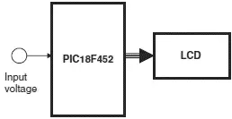
Figure 6.38: Block diagram of the project
The circuit diagram of the project is shown in Figure 6.39. The voltage to be measured (between 0 and 5V) is applied to port AN0 where this port is configured as an analog input in software. The LCD is connected to PORTC of the microcontroller as in the default four-wire connection. A potentiometer is used to adjust the contrast of the LCD display.
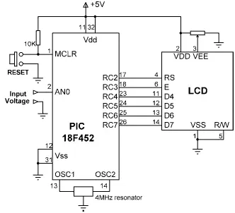
Figure 6.39: Circuit diagram of the project
Project PDL
The PDL of the project is shown in Figure 6.40. At the beginning of the program PORTC is configured as output and PORTA is configured as input. Then the LCD and the A/D converter are configured. The program then enters an endless loop where analog input voltage is converted to digital and displayed on the LCD. The process is repeated every second.
START
Configure PORTC as outputs
Configure PORTA as input
Configure the LCD
Configure the A/D converter
DO FOREVER
Read analog data (voltage) from channel 0
Format the data
Display the data (voltage)
Wait one second
ENDDO
END

Figure 6.40: PDL of the project
Project Program
The program is called SEVEN6.C, and the program listing is given in Figure 6.41. At the beginning of the program PORTC is defined as output and PORTA as input. Then the LCD is configured and the text “VOLTMETER” is displayed on the LCD for two seconds. The A/D is then configured by setting register ADCON1 to 0x80 so the A/D result is right-justified, Vref voltage is set to VDD (+5V), and all PORTA pins are configured as analog inputs.
/**************************************************************
VOLTMETER WITH LCD DISPLAY
============================
In this project an LCD is connected to PORTC. Also, input port AN0 is used as
analog input. Voltage to be measured is applied to AN0. The microcontroller
reads the analog voltage, converts into digital, and then displays on the LCD.
Analog input range is 0 to 5V. A PIC18F452 type microcontroller is used in
this project, operated with a 4MHz resonator.
Analog data is read using the Adc_Read built-in function. This function uses
the internal RC clock for A/D timing.
The LCD is connected to the microcontroller as follows:
Microcontroller LCD
RC7 D7
RC6 D6
RC5 D5
RC4 D4
RC3 Enable
RC2 RS
Author: Dogan Ibrahim
Date: July 2007
File: SEVEN6.C
**************************************************************/
//
// Start of MAIN Program. Configure LCD and A/D converter
//
void main() {
unsigned long Vin, mV;
unsigned char op[12];
unsigned char i,j,lcd[5];
TRISC = 0; // PORTC are outputs (LCD)
TRISA = 0xFF; // PORTA is input
//
// Configure LCD
//
Lcd_Init(&PORTC); // LCD is connected to PORTC
Lcd_Cmd(LCD_CLEAR);
Lcd_Out(1,1, "VOLTMETER");
Delay_ms(2000);
//
// Configure A/D converter. AN0 is used in this project
//
ADCON1 = 0x80; // Use AN0 and Vref=+5V
//
// Program loop
//
for(;;) // Endless loop
{
Lcd_Cmd(LCD_CLEAR);
Vin = Adc_Read(0); // Read from channel 0 (AN0)
Lcd_Out(1,1, "mV = "); // Display "mV = "
mV = (Vin * 5000) >> 10; // mv = Vin x 5000 / 1024
LongToStr(mV,op); // Convert to string in "op"
//
// Remove leading blanks
//
j=0;
for(i=0;i<=11;i++) {
if (op[i] != ' ') // If a blank
{
lcd[j]=op[i];
j++;
}
}
//
// Display result on LCD
//
Lcd_Out(1,6,lcd); // Output to LCD
Delay_ms(1000); // Wait 1 second
}
}
Figure 6.41: Program listing
The main program loop starts with a for statement. Inside this loop the LCD is cleared, and analog data is read from channel 0 (pin AN0) using the statement Adc_Read(0) . The converted digital data is stored in variable Vin which is declared as an unsigned long . The A/D converter is 10-bits wide and thus there are 1024 steps (0 to 1023) corresponding to the reference voltage of 5000mV. Each step corresponds to 5000mV/1024=4.88mV. Inside the loop, variable Vin is converted into millivolts by multiplying by 5000 and dividing into 1024. The division is done by shifting right by 10 digits. At this point variable mV contains the converted data in millivolts.
Function LongToStr is called to convert mV into a string in character array op . LongToStr converts a long variable into a string having a fixed width of eleven characters. If the resulting string is fewer than eleven characters, the left column of the data is filled with space characters.
The leading blanks are then removed and the data is stored in a variable called lcd . Function Lcd_Out is called to display the data on the LCD starting from column 5 of row 1. For example, if the measured voltage is 1267mV, it is displayed on the LCD as:
mV = 1267
A More Accurate Display
The voltage displayed in Figure 6.41 is not very accurate, since integer arithmetic has been performed in the calculation and the voltage is calculated by multiplying the A/D output by 5000 and then dividing the result by 1024 using integer division. Although the multiplication is accurate, the accuracy of the measurement is lost when the number is divided by 1024. A more accurate result can be obtained by scaling the number before it is displayed, as follows.
Читать дальшеИнтервал:
Закладка:
Похожие книги на «Advanced PIC Microcontroller Projects in C»
Представляем Вашему вниманию похожие книги на «Advanced PIC Microcontroller Projects in C» списком для выбора. Мы отобрали схожую по названию и смыслу литературу в надежде предоставить читателям больше вариантов отыскать новые, интересные, ещё непрочитанные произведения.


Обсуждение, отзывы о книге «Advanced PIC Microcontroller Projects in C» и просто собственные мнения читателей. Оставьте ваши комментарии, напишите, что Вы думаете о произведении, его смысле или главных героях. Укажите что конкретно понравилось, а что нет, и почему Вы так считаете.