Ibrahim Dogan - Advanced PIC Microcontroller Projects in C
Здесь есть возможность читать онлайн «Ibrahim Dogan - Advanced PIC Microcontroller Projects in C» весь текст электронной книги совершенно бесплатно (целиком полную версию без сокращений). В некоторых случаях можно слушать аудио, скачать через торрент в формате fb2 и присутствует краткое содержание. Город: Burlington, Год выпуска: 2008, ISBN: 2008, Издательство: Elsevier Ltd, Жанр: Программирование, Компьютерное железо, на английском языке. Описание произведения, (предисловие) а так же отзывы посетителей доступны на портале библиотеки ЛибКат.

- Название:Advanced PIC Microcontroller Projects in C
- Автор:
- Издательство:Elsevier Ltd
- Жанр:
- Год:2008
- Город:Burlington
- ISBN:978-0-7506-8611-2
- Рейтинг книги:5 / 5. Голосов: 1
-
Избранное:Добавить в избранное
- Отзывы:
-
Ваша оценка:
Advanced PIC Microcontroller Projects in C: краткое содержание, описание и аннотация
Предлагаем к чтению аннотацию, описание, краткое содержание или предисловие (зависит от того, что написал сам автор книги «Advanced PIC Microcontroller Projects in C»). Если вы не нашли необходимую информацию о книге — напишите в комментариях, мы постараемся отыскать её.
• Features 20 complete, tried and test projects
• Includes a CD-ROM of all the programs, hex listings, diagrams, and data sheets
Advanced PIC Microcontroller Projects in C — читать онлайн бесплатно полную книгу (весь текст) целиком
Ниже представлен текст книги, разбитый по страницам. Система сохранения места последней прочитанной страницы, позволяет с удобством читать онлайн бесплатно книгу «Advanced PIC Microcontroller Projects in C», без необходимости каждый раз заново искать на чём Вы остановились. Поставьте закладку, и сможете в любой момент перейти на страницу, на которой закончили чтение.
Интервал:
Закладка:
First, multiply the number Vin by a factor to remove the integer division. For example, since 5000/1024 = 4.88, we can multiply Vin by 488. For the display, we can calculate the integer part of the result by dividing the number into 100, and then the fractional part can be calculated as the remainder. The integer part and the fractional part can be displayed with a decimal point in between. This technique has been implemented in program SEVEN7.C as shown in Figure 6.42. In this program variables Vdec and Vfrac store the integer and the fractional parts of the number respectively. The decimal part is then converted into a string using function LongToStr and leading blanks are removed. The parts of the fractional number are called ch1 and ch2 . These are converted into characters by adding 48 (i.e., character “0”) and then displayed at the next cursor positions using the LCD command Lcd_Chr_Cp .
/**************************************************************
VOLTMETER WITH LCD DISPLAY
============================
In this project an LCD is connected to PORTC. Also, input port
AN0 is used as analog input. Voltage to be measured is applied
to AN0. The microcontroller reads the analog voltage, converts
into digital, and then displays on the LCD.
Analog input range is 0 to 5V. A PIC18F452 type microcontroller
is used in this project, operated with a 4MHz resonator.
Analog data is read using the Adc_Read built-in function. This
function uses the internal RC clock for A/D timing.
The LCD is connected to the microcontroller as follows:
Microcontroller LCD
RC7 D7
RC6 D6
RC5 D5
RC4 D4
RC3 Enable
RC2 RS
This program displays more accurate results than program SEVEN6.C.
The voltage is displayed as follows:
mV = nnnn.mm
Author: Dogan Ibrahim
Date: July 2007
File: SEVEN7.C
**************************************************************/
//
// Start of MAIN Program. Configure LCD and A/D converter
//
void main() {
unsigned long Vin, mV,Vdec,Vfrac;
unsigned char op[12];
unsigned char i,j,lcd[5],ch1,ch2;
TRISC = 0; // PORTC are outputs (LCD)
TRISA = 0xFF; // PORTA is input
//
// Configure LCD
//
Lcd_Init(&PORTC); // LCD is connected to PORTC
Lcd_Cmd(LCD_CLEAR);
Lcd_Out(1,1, "VOLTMETER");
Delay_ms(2000);
//
// Configure A/D converter. AN0 is used in this project
//
ADCON1 = 0x80; // Use AN0 and Vref=+5V
//
// Program loop
//
for(;;) // Endless loop
{
Lcd_Cmd(LCD_CLEAR);
Vin = Adc_Read(0); // Read from channel 0 (AN0)
Lcd_Out(1,1, "mV = "); // Display "mV = "
Vin = 488*Vin; // Scale up the result
Vdec = Vin / 100; // Decimal part
Vfrac = Vin % 100; // Fractional part
LongToStr(Vdec,op); // Convert Vdec to string in "op"
//
// Remove leading blanks
//
j=0;
for(i=0;i<=11;i++) {
if (op[i] != ' ') // If a blank
{
lcd[j]=op[i];
j++;
}
}
//
// Display result on LCD
//
Lcd_Out(1,6,lcd); // Output to LCD
Lcd_Out_Cp("."); // Display "."
ch1 = Vfrac / 10; // Calculate fractional part
ch2 = Vfrac % 10; // Calculate fractional part
Lcd_Chr_Cp(48+ch1); // Display fractional part
Lcd_Chr_Cp(48+ch2); // Display fractional part
Delay_ms(1000); // Wait 1 second
}
}

Figure 6.42: A more accurate program
We could also calculate and display more accurate results by using floating point arithmetic, but since this uses huge amounts of memory it should be avoided if possible.
PROJECT 6.9 — Calculator with Keypad and LCD
Project Description
Keypads are small keyboards used to enter numeric or alphanumeric data into microcontroller systems. Keypads are available in a variety of sizes and styles, from 2×2 to 4×4 or even bigger.
This project uses a 4×4 keypad (shown in Figure 6.43) and an LCD to design a simple calculator.
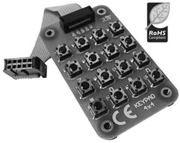
Figure 6.43: 4×4 keypad
Figure 6.44 shows the structure of the keypad used in this project which consists of sixteen switches formed in a 4×4 array and named numerals 0–9, Enter, “+”, “.”, “–”, “*”, and “/”. Rows and columns of the keypad are connected to PORTB of a microcontroller which scans the keypad to detect when a switch is pressed. The operation of the keypad is as follows:
• A logic 1 is applied to the first column via RB0.
• Port pins RB4 to RB7 are read. If the data is nonzero, a switch is pressed. If RB4 is 1, key 1 is pressed, if RB5 is 1, key 4 is pressed, if RB6 is 1, key 9 is pressed, and so on.
• A logic 1 is applied to the second column via RB1.
• Again, port pins RB4 to RB7 are read. If the data is nonzero, a switch is pressed. If RB4 is 1, key 2 is pressed, if RB5 is 1, key 6 is pressed, if RB6 is 1, key 0 is pressed, and so on.
• This process is repeated for all four columns continuously.
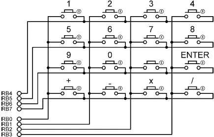
Figure 6.44: 4×4 keypad structure
In this project a simple integer calculator is designed. The calculator can add, subtract, multiply, and divide integer numbers and show the result on the LCD. The operation of the calculator is as follows: When power is applied to the system, the LCD displays text “CALCULATOR” for 2 seconds. Then text “No1:” is displayed in the first row of the LCD and the user is expected to type the first number and then press the ENTER key. Then text “No2:” is displayed in the second row of the LCD, where the user enters the second number and presses the ENTER key. After this, the appropriate operation key should be pressed. The result is displayed on the LCD for five seconds and then the LCD is cleared, ready for the next calculation. The example that follows shows how numbers 12 and 20 can be added:
No1: 12 ENTER
No2: 20 ENTER
Op: +
Res = 32
In this project the keyboard is labeled as follows:
1 2 3 4
5 6 7 8
9 0 ENTER
+ - X /
One of the keys, between 0 and ENTER, is not used in this project.
Project Hardware
Интервал:
Закладка:
Похожие книги на «Advanced PIC Microcontroller Projects in C»
Представляем Вашему вниманию похожие книги на «Advanced PIC Microcontroller Projects in C» списком для выбора. Мы отобрали схожую по названию и смыслу литературу в надежде предоставить читателям больше вариантов отыскать новые, интересные, ещё непрочитанные произведения.


Обсуждение, отзывы о книге «Advanced PIC Microcontroller Projects in C» и просто собственные мнения читателей. Оставьте ваши комментарии, напишите, что Вы думаете о произведении, его смысле или главных героях. Укажите что конкретно понравилось, а что нет, и почему Вы так считаете.