Ibrahim Dogan - Advanced PIC Microcontroller Projects in C
Здесь есть возможность читать онлайн «Ibrahim Dogan - Advanced PIC Microcontroller Projects in C» весь текст электронной книги совершенно бесплатно (целиком полную версию без сокращений). В некоторых случаях можно слушать аудио, скачать через торрент в формате fb2 и присутствует краткое содержание. Город: Burlington, Год выпуска: 2008, ISBN: 2008, Издательство: Elsevier Ltd, Жанр: Программирование, Компьютерное железо, на английском языке. Описание произведения, (предисловие) а так же отзывы посетителей доступны на портале библиотеки ЛибКат.

- Название:Advanced PIC Microcontroller Projects in C
- Автор:
- Издательство:Elsevier Ltd
- Жанр:
- Год:2008
- Город:Burlington
- ISBN:978-0-7506-8611-2
- Рейтинг книги:5 / 5. Голосов: 1
-
Избранное:Добавить в избранное
- Отзывы:
-
Ваша оценка:
Advanced PIC Microcontroller Projects in C: краткое содержание, описание и аннотация
Предлагаем к чтению аннотацию, описание, краткое содержание или предисловие (зависит от того, что написал сам автор книги «Advanced PIC Microcontroller Projects in C»). Если вы не нашли необходимую информацию о книге — напишите в комментариях, мы постараемся отыскать её.
• Features 20 complete, tried and test projects
• Includes a CD-ROM of all the programs, hex listings, diagrams, and data sheets
Advanced PIC Microcontroller Projects in C — читать онлайн бесплатно полную книгу (весь текст) целиком
Ниже представлен текст книги, разбитый по страницам. Система сохранения места последней прочитанной страницы, позволяет с удобством читать онлайн бесплатно книгу «Advanced PIC Microcontroller Projects in C», без необходимости каждый раз заново искать на чём Вы остановились. Поставьте закладку, и сможете в любой момент перейти на страницу, на которой закончили чтение.
Интервал:
Закладка:
RS232 serial communication is a form of asynchronous data transmission where data is sent character by character. Each character is preceded with a start bit, seven or eight data bits, an optional parity bit, and one or more stop bits. The most common format is eight data bits, no parity bit, and one stop bit. The least significant data bit is transmitted first, and the most significant bit is transmitted last.
A logic high is defined at –12V, and a logic 0 is at +12V. Figure 6.50 shows how character “A” (ASCII binary pattern 0010 0001) is transmitted over a serial line. The line is normally idle at –12V. The start bit is first sent by the line going from high to low. Then eight data bits are sent, starting from the least significant bit. Finally, the stop bit is sent by raising the line from low to high.
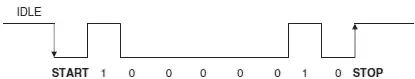
Figure 6.50: Sending character “A” in serial format
In a serial connection, a minimum of three lines is used for communication: transmit (TX), receive (RX), and ground (GND). Serial devices are connected to each other using two types of connectors: 9-way and 25-way. Table 6.11 shows the TX, RX, and GND pins of each type of connectors. The connectors used in RS232 serial communication are shown in Figure 6.51.
Table 6.11: Minimum required pins for serial communication
| 9-pin connector | |
|---|---|
| Pin | Function |
| 2 | Transmit (TX) |
| 3 | Receive (RX) |
| 5 | Ground (GND) |
| 25-pin connector | |
|---|---|
| Pin | Function |
| 2 | Transmit (TX) |
| 3 | Receive (RX) |
| 7 | Ground (GND) |
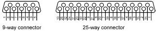
Figure 6.51: RS232 connectors
As just described, RS232 voltage levels are at ±12V. However, microcontroller input-output ports operate at 0 to +5V voltage levels, so the voltage levels must be translated before a microcontroller can be connected to a RS232 compatible device. Thus the output signal from the microcontroller has to be converted to ±12V, and the input from an RS232 device must be converted into 0 to +5V before it can be connected to a microcontroller. This voltage translation is normally done with special RS232 voltage converter chips. One such popular chip is the MAX232, a dual converter chip having the pin configuration shown in Figure 6.52. The device requires four external 1μF capacitors for its operation.
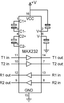
Figure 6.52: MAX232 pin configuration
In the PIC18 series of microcontrollers, serial communication can be handled either in hardware or in software. The hardware option is easy. PIC18 microcontrollers have built-in USART (universal synchronous asynchronous receiver transmitter) circuits providing special input-output pins for serial communication. For serial communication all the data transmission is handled by the USART, but the USART has to be configured before receiving and transmitting data. With the software option, all the serial bit timing is handled in software, and any input-output pin can be programmed and used for serial communication.
In this project a PC is connected to the microcontroller using an RS232 cable. The project operates as a simple integer calculator where data is sent to the microcontroller using the PC keyboard and displayed on the PC monitor.
CALCULATOR PROGRAM
Enter First Number: 12
Enter Second Number: 2
Enter Operation: +
Result = 14
Project Hardware
Figure 6.53 shows the block diagram of the project. The circuit diagram is given in Figure 6.54. This project uses a PIC18F452 microcontroller with a 4MHz resonator, and the built-in USART is used for serial communication. The serial communication lines of the microcontroller (RC6 and RC7) are connected to a MAX232 voltage translator chip and then to the serial input port (COM1) of a PC using a 9-pin connector.
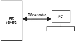
Figure 6.53: Block diagram of the project
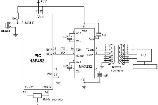
Figure 6.54: Circuit diagram of the project
Project PDL
The PDL of the project is shown in Figure 6.55. The project consists of a main program and two functions called Newline and Text_To_User . Function Newline sends a carriage-return and line-feed to the serial port. Function Text_To_User sends a text message to USART. The main program receives two numbers and the operation to be performed from the PC keyboard. The numbers are echoed on the PC monitor. The result of the operation is also displayed on the monitor.
Function Newline:
START
Send carriage-return to USART
Send line-feed to USART
END
Function Text_To_Usart
START
Get text from the argument
Send text to USART
END
Main program:
START
Configure USART to 9600 Baud
DO FOREVER
Display “CALCULATOR PROGRAM”
Display “Enter First Number: ”
Read first number
Display “Enter Second Number: ”
Read second number
Display “Operation: ”
Read operation
Perform operation
Display “Result= ”
Display the result
ENDDO
END

Figure 6.55: Project PDL
Project Program
The program listing of the project is shown in Figure 6.56. The program consists of a main program and two functions called Newline and Text_To_Usart . Function Newline sends a carriage return and line feed to the USART to move the cursor to the next line. Function Text_To_Usart sends a text message to the USART.
/*********************************************************************
CALCULATOR WITH PC INTERFACE
==============================
In this project a PC is connected to a PIC18F452 microcontroller. The
project is a simple integer calculator. User enters the numbers using
the PC keyboard. Results are displayed on the PC monitor.
The following operations can be performed:
+ − * /
This program uses the built in USART of the microcontroller. The USART is
configured to operate with 9600 Baud rate.
The serial TX pin is RC6 and the serial RX pin is RC7.
Author: Dogan Ibrahim
Date: July 2007
File: SERIAL1.C
*********************************************************************/
#define Enter 13
Интервал:
Закладка:
Похожие книги на «Advanced PIC Microcontroller Projects in C»
Представляем Вашему вниманию похожие книги на «Advanced PIC Microcontroller Projects in C» списком для выбора. Мы отобрали схожую по названию и смыслу литературу в надежде предоставить читателям больше вариантов отыскать новые, интересные, ещё непрочитанные произведения.


Обсуждение, отзывы о книге «Advanced PIC Microcontroller Projects in C» и просто собственные мнения читателей. Оставьте ваши комментарии, напишите, что Вы думаете о произведении, его смысле или главных героях. Укажите что конкретно понравилось, а что нет, и почему Вы так считаете.