Ibrahim Dogan - Advanced PIC Microcontroller Projects in C
Здесь есть возможность читать онлайн «Ibrahim Dogan - Advanced PIC Microcontroller Projects in C» весь текст электронной книги совершенно бесплатно (целиком полную версию без сокращений). В некоторых случаях можно слушать аудио, скачать через торрент в формате fb2 и присутствует краткое содержание. Город: Burlington, Год выпуска: 2008, ISBN: 2008, Издательство: Elsevier Ltd, Жанр: Программирование, Компьютерное железо, на английском языке. Описание произведения, (предисловие) а так же отзывы посетителей доступны на портале библиотеки ЛибКат.

- Название:Advanced PIC Microcontroller Projects in C
- Автор:
- Издательство:Elsevier Ltd
- Жанр:
- Год:2008
- Город:Burlington
- ISBN:978-0-7506-8611-2
- Рейтинг книги:5 / 5. Голосов: 1
-
Избранное:Добавить в избранное
- Отзывы:
-
Ваша оценка:
Advanced PIC Microcontroller Projects in C: краткое содержание, описание и аннотация
Предлагаем к чтению аннотацию, описание, краткое содержание или предисловие (зависит от того, что написал сам автор книги «Advanced PIC Microcontroller Projects in C»). Если вы не нашли необходимую информацию о книге — напишите в комментариях, мы постараемся отыскать её.
• Features 20 complete, tried and test projects
• Includes a CD-ROM of all the programs, hex listings, diagrams, and data sheets
Advanced PIC Microcontroller Projects in C — читать онлайн бесплатно полную книгу (весь текст) целиком
Ниже представлен текст книги, разбитый по страницам. Система сохранения места последней прочитанной страницы, позволяет с удобством читать онлайн бесплатно книгу «Advanced PIC Microcontroller Projects in C», без необходимости каждый раз заново искать на чём Вы остановились. Поставьте закладку, и сможете в любой момент перейти на страницу, на которой закончили чтение.
Интервал:
Закладка:
Read data from Port 1
Send data to PORT 2
Wait for 1 second
ENDDO
6.1.5 REPEAT-UNTIL
REPEAT-UNTIL is another control construct used in PDL codes. In the following example the program waits until a switch value is equal to 1.
REPEAT
Turn on buzzer
Read switch value
UNTIL switch = 1
Notice that the REPEAT-UNTIL loop is always executed at least once, and more than once if the condition at the end of the loop is not met.
PROJECT 6.1 — Chasing LEDs
Project Description
In this project eight LEDs are connected to PORTC of a PIC18F452-type microcontroller, and the microcontroller is operated from a 4MHz resonator. When power is applied to the microcontroller (or when the microcontroller is reset), the LEDs turn ON alternately in an anticlockwise manner where only one LED is ON at any time. There is a one-second delay between outputs so the LEDs can be seen turning ON and OFF.
An LED can be connected to a microcontroller output port in two different modes: current sinking and current sourcing.
As shown in Figure 6.1, in current sinking mode the anode leg of the LED is connected to the +5V supply, and the cathode leg is connected to the microcontroller output port through a current limiting resistor.
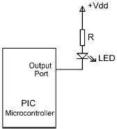
Figure 6.1: LED connected in current sinking mode
The voltage drop across an LED varies between 1.4V and 2.5V, with a typical value of 2V. The brightness of the LED depends on the current through the LED, and this current can vary between 8 and 16mA, with a typical value of 10mA.
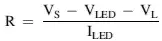
The LED is turned ON when the output of the microcontroller is at logic 0 so the current flows through the LED. Assuming the microcontroller output voltage is about 0.4V when the output is low, we can calculate the value of the required resistor as follows:
 (6.1)
(6.1)
where
V Sis the supply voltage (5V)
V LEDis the voltage drop across the LED (2V)
V Lis the maximum output voltage when the output port is low (0.4V)
I LEDis the current through the LED (10mA)
Substituting the values into Equation (6.1) we get,
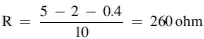
The nearest physical resistor is 270 ohms.
As shown in Figure 6.2, in current sourcing mode the anode leg of the LED is connected to the microcontroller output port and the cathode leg is connected to the ground through a current limiting resistor.
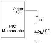
Figure 6.2: LED connected in current sourcing mode
In this mode the LED is turned ON when the microcontroller output port is at logic 1 (i.e., +5V). In practice, the output voltage is about 4.85V and the value of the resistor can be determined as:
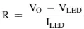 (6.2)
(6.2)
where
V Ois the output voltage of the microcontroller port when at logic 1 (+4.85V).
Thus, the value of the required resistor is:
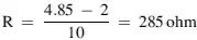
The nearest physical resistor is 290 ohm.
Project Hardware
The circuit diagram of the project is shown in Figure 6.3. LEDs are connected to PORTC in current sourcing mode with eight 290-ohm resistors. A 4MHz resonator is connected between the OSC1 and OSC2 pins. Also, an external reset push button is connected to the MCLR input to reset the microcontroller when required.
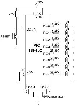
Figure 6.3: Circuit diagram of the project
Project PDL
The PDL of this project is very simple and is given in Figure 6.4.
START
Configure PORTC pins as output
Initialize J = 1
DO FOREVER
Set PORTC = J
Shift left J by 1 digit
IF J = 0 THEN
J = 1
ENDIF
Wait 1 second
ENDDO
END

Figure 6.4: PDL of the project
Project Program
The program is named as LED1.C, and the program listing is given in Figure 6.5. At the beginning of the program PORTC pins are configured as outputs by setting TRISC = 0. Then an endless for loop is formed, and the LEDs are turned ON alternately in an anticlockwise manner to create a chasing effect. The program checks continuously so that when LED 7 is turned ON, the next LED to be turned ON is LED 0.
This program can be compiled using the mikroC compiler. Project settings should be configured to 4MHz clock, XT crystal mode, and WDT OFF. The HEX file (LED1.HEX) should be loaded to the PIC18F452 microcontroller using either an in-circuit debugger or a programming device.
/*****************************************************************************
CHASING LEDS
============
In this project 8 LEDs are connected to PORTC of a PIC18F452 microcontroller
and the microcontroller is operated from a 4MHz resonator. The program turns
on the LEDs in an anti-clockwise manner with one second delay between each
output. The net result is that the LEDs seem to be chasing each other.
Author: Dogan Ibrahim
Date: July 2007
File: LED1.C
******************************************************************************/
void main() {
unsigned char J = 1;
TRISC = 0;
for(;;) // Endless loop
{
PORTC = J; // Send J to PORTC
Delay_ms(1000); // Delay 1 second
J = J << 1; // Shift left J
if (J == 0) J = 1; // If last LED, move to first LED
}
}
Figure 6.5: Program listing
Further Development
The project can be modified such that the LEDs chase each other in both directions. For example, if the LEDs are moving in an anticlockwise direction, the direction can be changed so that when LED RB7 is ON the next LED to turn ON is RB6, when RB6 is ON the next is RB5, and so on.
PROJECT 6.2 — LED Dice
Project Description
This is a simple dice project based on LEDs, a push-button switch, and a PIC18F452 microcontroller operating with a 4MHz resonator. The block diagram of the project is shown in Figure 6.6.
Читать дальшеИнтервал:
Закладка:
Похожие книги на «Advanced PIC Microcontroller Projects in C»
Представляем Вашему вниманию похожие книги на «Advanced PIC Microcontroller Projects in C» списком для выбора. Мы отобрали схожую по названию и смыслу литературу в надежде предоставить читателям больше вариантов отыскать новые, интересные, ещё непрочитанные произведения.


Обсуждение, отзывы о книге «Advanced PIC Microcontroller Projects in C» и просто собственные мнения читателей. Оставьте ваши комментарии, напишите, что Вы думаете о произведении, его смысле или главных героях. Укажите что конкретно понравилось, а что нет, и почему Вы так считаете.