Ibrahim Dogan - Advanced PIC Microcontroller Projects in C
Здесь есть возможность читать онлайн «Ibrahim Dogan - Advanced PIC Microcontroller Projects in C» весь текст электронной книги совершенно бесплатно (целиком полную версию без сокращений). В некоторых случаях можно слушать аудио, скачать через торрент в формате fb2 и присутствует краткое содержание. Город: Burlington, Год выпуска: 2008, ISBN: 2008, Издательство: Elsevier Ltd, Жанр: Программирование, Компьютерное железо, на английском языке. Описание произведения, (предисловие) а так же отзывы посетителей доступны на портале библиотеки ЛибКат.

- Название:Advanced PIC Microcontroller Projects in C
- Автор:
- Издательство:Elsevier Ltd
- Жанр:
- Год:2008
- Город:Burlington
- ISBN:978-0-7506-8611-2
- Рейтинг книги:5 / 5. Голосов: 1
-
Избранное:Добавить в избранное
- Отзывы:
-
Ваша оценка:
Advanced PIC Microcontroller Projects in C: краткое содержание, описание и аннотация
Предлагаем к чтению аннотацию, описание, краткое содержание или предисловие (зависит от того, что написал сам автор книги «Advanced PIC Microcontroller Projects in C»). Если вы не нашли необходимую информацию о книге — напишите в комментариях, мы постараемся отыскать её.
• Features 20 complete, tried and test projects
• Includes a CD-ROM of all the programs, hex listings, diagrams, and data sheets
Advanced PIC Microcontroller Projects in C — читать онлайн бесплатно полную книгу (весь текст) целиком
Ниже представлен текст книги, разбитый по страницам. Система сохранения места последней прочитанной страницы, позволяет с удобством читать онлайн бесплатно книгу «Advanced PIC Microcontroller Projects in C», без необходимости каждый раз заново искать на чём Вы остановились. Поставьте закладку, и сможете в любой момент перейти на страницу, на которой закончили чтение.
Интервал:
Закладка:
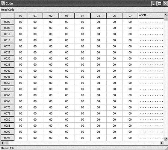
Figure 5.62: Display of Code memory
View the Statistics The Statistics window is invoked from the mikroC IDE dropdown menu and it displays various statistical data about our program. To view the statistics window, click View→View Statistics . Figure 5.63 shows an example Statistics window, which consists of several tabs. The Memory Usage tab displays the amount of RAM (data memory) and ROM (code memory) used. The Procedures tabs display information about the size and locations of the procedures. The RAM and ROM tabs display memory usage in detail.
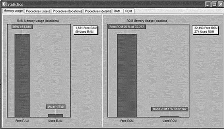
Figure 5.63: Display of Statistics window
5.4 Summary
This chapter has described the PIC microcontroller software development tools (such as text editors, assemblers, compilers, and simulators) and hardware development tools (including development boards and kits, programming devices, in-circuit debuggers, and in-circuit emulators). The mikroC compiler was used in the examples and projects. The steps in developing and testing a mikroC-based C program were presented both with and without a hardware in-circuit debugger, followed by an example of how to use the BIGPIC4 development board, with the on-board in-circuit debugger enabled.
5.5 Exercises
1. Describe the phases of the microcontroller-based system development cycle.
2. Describe briefly the microcontroller development tools.
3. Explain the advantages and disadvantages of assemblers and compilers.
4. Explain why a simulator can be a useful tool while developing a microcontroller-based product.
5. Explain in detail what a device programmer is. Give some examples of device programmers for the PIC18 series of microcontrollers.
6. Describe briefly the differences between in-circuit debuggers and in-circuit emulators. List the advantages and disadvantages of both debugging tools.
7. Enter the following program into the mikroC IDE and compile the program, correcting any syntax errors. Then, using the software ICD, simulate the operation of the program by single-stepping through the code, and observe the values of the variables during the simulation.
/*=====================================
A SIMPLE LED PROJECT
This program flashes the 8 LEDs connected to PORTC of a PIC18F452
microcontroller.
=====================================*/
void main() {
TRISC = 0; // PORTC is output
do {
PORTC = 0xFF; // Turn ON LEDs on PORTC
PORTC = 0; // Turn OFF LEDs on PORTC
} while(1); // Endless loop
}
8. Describe the steps in using the mikroICD in-circuit debugger.
9. The following C program contains some deliberately introduced errors. Compile the program to find and correct the errors.
void main() {
unsigned char i,j,k
i = 10;
j = i + 1;
for(i = 0; i < 10; i++) {
Sum = Sum + i;
j++
}
}
}
10. The following C program contains some deliberately introduced errors. Compile the program to find and correct the errors.
int add(int a, int b) {
result = a + b
}
void main() {
int p,q;
p = 12;
q = 10;
z = add(p, q)
z++;
for(i = 0; i < z; i++) p++
}
}
CHAPTER 6
Simple PIC18 Projects
In this chapter we will look at the design of simple PIC18 microcontroller-based projects, with the idea of becoming familiar with basic interfacing techniques and learning how to use the various microcontroller peripheral registers. We will look at the design of projects using LEDs, push-button switches, keyboards, LED arrays, sound devices, and so on, and we will develop programs in C language using the mikroC compiler. The hardware is designed on a low-cost breadboard, but development kits such as BIGPIC4 can be used for these projects. We will start with very simple projects and proceed to more complex ones. It is recommended that the reader moves through the projects in their given order. The following are provided for each project:
• Description of the program
• Description of the hardware
• Circuit diagram
• Algorithm description (in PDL)
• Program listing
• Suggestions for further development
The program’s algorithm can be described in a variety of graphic and text-based methods, some of the common ones being a flow diagram, a structure chart, and program description language. In this book we are using program description language (PDL).
6.1 Program Description Language (PDL)
Program description language (PDL) is free-format English-like text which describes the flow of control in a program. PDL is not a programming language but rather is a tool which helps the programmer to think about the logic of the program before the program has been developed. Commonly used PDL keywords are described as follows.
6.1.1 START-END
Every PDL program description (or subprogram) should begin with a START keyword and terminate with an END keyword. The keywords in a PDL code should be highlighted in bold to make the code more clear. It is also a good practice to indent program statements between PDL keywords in order to enhance the readability of the code.
START
......
......
END
6.1.2 Sequencing
For normal sequencing in a program, write the statements as short English text as if you are describing the program.
Turn on the LED
Wait 1 second
Turn off the LED
6.1.3 IF-THEN-ELSE-ENDIF
Use IF, THEN, ELSE, and ENDIF keywords to describe the flow of control in a program.
IF switch = 1 THEN
Turn on LED 1
ELSE
Turn on LED 2
Start the motor
ENDIF
6.1.4 DO-ENDDO
Use Do and ENDDO keywords to show iteration in the PDL code.
To create an unconditional loop in a program we can write:
Turn on LED
DO 10 times
Set clock to 1
Wait for 10ms
Set clock to 0
ENDDO
A variation of the DO-ENDDO construct is to use other keywords like DO-FOREVER, DO-UNTIL, etc. as shown in the following examples.
To create a conditional loop in a program we can write:
Turn off buzzer
IF switch = 1 THEN
DO UNTIL Port 1 = 1
Turn on LED
Wait for 10ms
Read Port 1
ENDDO
ENDIF
The following construct can be used when an endless loop is required:
DO FOREVER
Интервал:
Закладка:
Похожие книги на «Advanced PIC Microcontroller Projects in C»
Представляем Вашему вниманию похожие книги на «Advanced PIC Microcontroller Projects in C» списком для выбора. Мы отобрали схожую по названию и смыслу литературу в надежде предоставить читателям больше вариантов отыскать новые, интересные, ещё непрочитанные произведения.


Обсуждение, отзывы о книге «Advanced PIC Microcontroller Projects in C» и просто собственные мнения читателей. Оставьте ваши комментарии, напишите, что Вы думаете о произведении, его смысле или главных героях. Укажите что конкретно понравилось, а что нет, и почему Вы так считаете.