Ibrahim Dogan - Advanced PIC Microcontroller Projects in C
Здесь есть возможность читать онлайн «Ibrahim Dogan - Advanced PIC Microcontroller Projects in C» весь текст электронной книги совершенно бесплатно (целиком полную версию без сокращений). В некоторых случаях можно слушать аудио, скачать через торрент в формате fb2 и присутствует краткое содержание. Город: Burlington, Год выпуска: 2008, ISBN: 2008, Издательство: Elsevier Ltd, Жанр: Программирование, Компьютерное железо, на английском языке. Описание произведения, (предисловие) а так же отзывы посетителей доступны на портале библиотеки ЛибКат.

- Название:Advanced PIC Microcontroller Projects in C
- Автор:
- Издательство:Elsevier Ltd
- Жанр:
- Год:2008
- Город:Burlington
- ISBN:978-0-7506-8611-2
- Рейтинг книги:5 / 5. Голосов: 1
-
Избранное:Добавить в избранное
- Отзывы:
-
Ваша оценка:
Advanced PIC Microcontroller Projects in C: краткое содержание, описание и аннотация
Предлагаем к чтению аннотацию, описание, краткое содержание или предисловие (зависит от того, что написал сам автор книги «Advanced PIC Microcontroller Projects in C»). Если вы не нашли необходимую информацию о книге — напишите в комментариях, мы постараемся отыскать её.
• Features 20 complete, tried and test projects
• Includes a CD-ROM of all the programs, hex listings, diagrams, and data sheets
Advanced PIC Microcontroller Projects in C — читать онлайн бесплатно полную книгу (весь текст) целиком
Ниже представлен текст книги, разбитый по страницам. Система сохранения места последней прочитанной страницы, позволяет с удобством читать онлайн бесплатно книгу «Advanced PIC Microcontroller Projects in C», без необходимости каждый раз заново искать на чём Вы остановились. Поставьте закладку, и сможете в любой момент перейти на страницу, на которой закончили чтение.
Интервал:
Закладка:
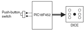
Figure 6.6: Block diagram of the project
As shown in Figure 6.7, the LEDs are organized such that when they turn ON, they indicate numbers as on a real dice. Operation of the project is as follows: The LEDs are all OFF to indicate that the system is ready to generate a new number. Pressing the switch generates a random number between 1 and 6 which is displayed on the LEDs for 3 seconds. After 3 seconds the LEDs turn OFF again.
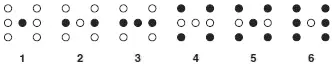
Figure 6.7: LED dice
Project Hardware
The circuit diagram of the project is shown in Figure 6.8. Seven LEDs representing the faces of a dice are connected to PORTC of a PIC18F452 microcontroller in current sourcing mode using 290-ohm current limiting resistors. A push-button switch is connected to bit 0 of PORTB (RB0) using a pull-up resistor. The microcontroller is operated from a 4MHz resonator connected between pins OSC1 and OSC2. The microcontroller is powered from a +9V battery, and a 78L05-type voltage regulator IC is used to obtain the +5V supply required for the microcontroller.
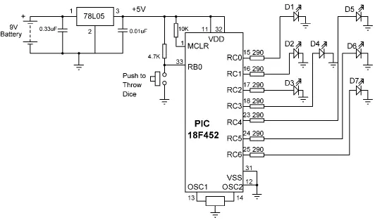
Figure 6.8: Circuit diagram of the project
Project PDL
The operation of the project is described in PDL in Figure 6.9. At the beginning of the program PORTC pins are configured as outputs and bit 0 of PORTB (RB0) is configured as input. The program then executes in a loop continuously and increments a variable between 1 and 6. The state of the push-button switch is checked and when the switch is pressed (switch output at logic 0), the current number is sent to the LEDs. A simple array is used to find out the LEDs to be turned ON corresponding to the dice number.
START
Create DICE table
Configure PORTC as outputs
Configure RB0 as input
Set J = 1
DO FOREVER
IF button pressed THEN
Get LED pattern from DICE table
Turn ON required LEDs
Wait 3 seconds
Set J = 0
Turn OFF all LEDs
ENDIF
Increment J
IF J = 7 THEN
Set J = 1
ENDIF
ENDDO
END

Figure 6.9: PDL of the project
Table 6.1 gives the relationship between a dice number and the corresponding LEDs to be turned ON to imitate the faces of a real dice. For example, to display number 1 (i.e., only the middle LED is ON), we have to turn on D4. Similarly, to display number 4, the LEDs to turn ON are D1, D3, D5, and D7.
Table 6.1: Dice number and LEDs to be turned ON
| Required number | LEDs to be turned on |
|---|---|
| 1 | D4 |
| 2 | D2, D6 |
| 3 | D2, D4, D6 |
| 4 | D1, D3, D5, D7 |
| 5 | D1, D3, D4, D5, D7 |
| 6 | D1, D2, D3, D5, D6, D7 |
The relationship between the required number and the data to be sent to PORTC to turn on the correct LEDs is given in Table 6.2. For example, to display dice number 2, we have to send hexadecimal 0x22 to PORTC. Similarly, to display number 5, we have to send hexadecimal 0x5D to PORTC, and so on.
Table 6.2: Required number and PORTC data
| Required number | PORTB data (Hex) |
|---|---|
| 1 | 0x08 |
| 2 | 0x22 |
| 3 | 0x2A |
| 4 | 0x55 |
| 5 | 0x5D |
| 6 | 0x77 |
Project Program
The program is called LED2.C, and the program listing is given in Figure 6.10. At the beginning of the program Switch is defined as bit 0 of PORTB, and Pressed is defined as 0. The relationships between the dice numbers and the LEDs to be turned on are stored in an array called DICE . Variable J is used as the dice number. Variable Pattern is the data sent to the LEDs. Program then enters an endless for loop where the value of variable J is incremented very fast between 1 and 6. When the push-button switch is pressed, the LED pattern corresponding to the current value of J is read from the array and sent to the LEDs. The LEDs remain in this state for 3 seconds (using function Delay_ms with the argument set to 3000ms), after which they all turn OFF. The system is then ready to generate a new dice number.
/*****************************************************************************
SIMPLE DICE
===========
In this project 7 LEDs are connected to PORTC of a PIC18F452 microcontroller
and the microcontroller is operated from a 4MHz resonator. The LEDs are
organized as the faces of a real dice. When a push-button switch connected to
RB0 is pressed a dice pattern is displayed on the LEDs. The display remains in
this state for 3 seconds and after this period the LEDs all turn OFF to
indicate that the system is ready for the button to be pressed again.
Author: Dogan Ibrahim
Date: July 2007
File: LED2.C
*****************************************************************************/
#define Switch PORTB.F0
#define Pressed 0
void main() {
unsigned char J = 1;
unsigned char Pattern;
unsigned char DICE[] = {0,0x08,0x22,0x2A,0x55,0x5D,0x77};
TRISC = 0; // PORTC outputs
TRISB = 1; // RB0 input
PORTC = 0; // Turn OFF all LEDs
for(;;) // Endless loop
{
if(Switch == Pressed) // Is switch pressed ?
{
Pattern = DICE[J]; // Get LED pattern
PORTC = Pattern; // Turn on LEDs
Delay_ms(3000); // Delay 3 second
PORTC = 0; // Turn OFF all LEDs
J = 0; // Initialize J
}
J++; // Increment J
if (J == 7) J = 1; // Back to 1 if > 6
}
}
Figure 6.10: Program listing
Using a Pseudorandom Number Generator
In the preceding project the value of variable J changes very fast among the numbers between 1 and 6, so we can say that the numbers generated are random (i.e., new numbers do not depend on the previous numbers).
A pseudorandom number generator function can also be used to generate the dice numbers. The modified program listing is shown in Figure 6.11. In this program a function called Number generates the dice numbers. The function receives the upper limit of the numbers to be generated (6 in this example) and also a seed value which defines the number set to be generated. In this example, the seed is set to 1. Every time the function is called, a number between 1 and 6 is generated.
Читать дальшеИнтервал:
Закладка:
Похожие книги на «Advanced PIC Microcontroller Projects in C»
Представляем Вашему вниманию похожие книги на «Advanced PIC Microcontroller Projects in C» списком для выбора. Мы отобрали схожую по названию и смыслу литературу в надежде предоставить читателям больше вариантов отыскать новые, интересные, ещё непрочитанные произведения.


Обсуждение, отзывы о книге «Advanced PIC Microcontroller Projects in C» и просто собственные мнения читателей. Оставьте ваши комментарии, напишите, что Вы думаете о произведении, его смысле или главных героях. Укажите что конкретно понравилось, а что нет, и почему Вы так считаете.