Zark Bedalov - Practical Power Plant Engineering
Здесь есть возможность читать онлайн «Zark Bedalov - Practical Power Plant Engineering» — ознакомительный отрывок электронной книги совершенно бесплатно, а после прочтения отрывка купить полную версию. В некоторых случаях можно слушать аудио, скачать через торрент в формате fb2 и присутствует краткое содержание. Жанр: unrecognised, на английском языке. Описание произведения, (предисловие) а так же отзывы посетителей доступны на портале библиотеки ЛибКат.

- Название:Practical Power Plant Engineering
- Автор:
- Жанр:
- Год:неизвестен
- ISBN:нет данных
- Рейтинг книги:5 / 5. Голосов: 1
-
Избранное:Добавить в избранное
- Отзывы:
-
Ваша оценка:
Practical Power Plant Engineering: краткое содержание, описание и аннотация
Предлагаем к чтению аннотацию, описание, краткое содержание или предисловие (зависит от того, что написал сам автор книги «Practical Power Plant Engineering»). Если вы не нашли необходимую информацию о книге — напишите в комментариях, мы постараемся отыскать её.
The book explores the most relevant topics and reviews the industry standards and established engineering practices. For example, the author leads the reader through the application of MV switchgear, MV controllers, MCCs and distribution lines in building plant power distribution systems, including calculations of interrupting duty for breakers and contactors. The text also contains useful information on the various types of concentrated and photovoltaic solar plants as well as wind farms with DFIG turbines. This important book:
• Explains why and how to select the proper ratings for electrical equipment for specific applications
• Includes information on the critical requirements for designing power systems to meet the performance requirements
• Presents tests of the electrical equipment that prove it is built to the required standards and will meet plant-specific operating requirements
Written for both professional engineers early in their career and experienced engineers,
is a must-have resource that offers the information needed to apply the concepts of power plant engineering in the real world.
Practical Power Plant Engineering — читать онлайн ознакомительный отрывок
Ниже представлен текст книги, разбитый по страницам. Система сохранения места последней прочитанной страницы, позволяет с удобством читать онлайн бесплатно книгу «Practical Power Plant Engineering», без необходимости каждый раз заново искать на чём Вы остановились. Поставьте закладку, и сможете в любой момент перейти на страницу, на которой закончили чтение.
Интервал:
Закладка:
2.4.2 Line Conductor
We received the conductor (name) information from the utility. It will be a single Hawk ACSR (aluminum conductor steel reinforced) conductor. The overhead conductors are symbolically called by the names of birds. The data for the Hawk conductor can be obtained from online sources. The best source of data for the conductors is the old T&D Westinghouse handbook, from which we find the following data:
HawkType: ACSR, 477 kcmilStranding: 26/7Ampacity: 660 AResistance: 0.135 Ω/kmInductive reactance: 0.24 Ω/kmCapacitive reactance: 0.188 Ω/km
The Hawk line carrying capacity is well in excess of our plant requirements. Utilities like to build lines with sufficient capacity for future expansions. The maximum expected current from the plant at 230 kV is 100 A at 40 MVA. The line length from the plant to the local utility source of generation is estimated at 120 km.
Calculate the line parameters in pu for the system studies:Now, calculate line characteristics in pu(2.1)
Convert line characteristics (pu) from one MVA base to another:(2.2) (2.3)
Convert line characteristics (Ω) from one system voltage kV base to another:(2.4) (2.5)
The utility “informed” us that fault level at our plant bus, projected for the future with possible expansion is 10 kA at 230 kV. This is calculated approximately as: MVA sc= 4000 MVA.
Therefore, we can now calculate the source impedanceat our 230 kV bus as follows:
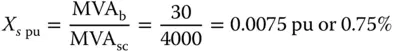
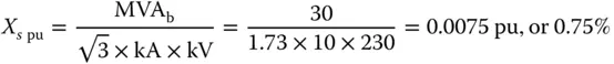
Or pu source impedance if kA fault interrupting current from the source (power utility) is given:
This source impedance will be used in our computer studies to represent the utility at our plant point of interface. It is a conservative value that will provide plenty of margin in our calculation.
However, for our quick hand calculations and for our interrupting ratings of the switchgear, we will rate our equipment on a conservative basis of an infinite fault level from the utility (zero source impedance). Therefore, the utility can now be called an Infinite bus at the point of interface with our plant.
If we now calculate the fault MVA scfrom the Utility on our selected MVA bbase, it is:

2.4.3 HV Circuit Breaker Fault Interrupting
Now we can determine the incoming 230 kV breaker as follows: It has to have interrupting capacity of at least 4000 A. We select 3 phase, 245 kV, 1200 A, 40 kA fault interrupting, basic impulse level BIL: 1050 kV peak (see Figure 2.5).
Why 40 kA? This may sound too excessive for our requirements, but these are the ratings at the low end for the 230 kV equipment.
The transformer differential protection scheme and metering would need current transformers (CTs) on the grid side of the HV breaker.
2.4.4 Double or Single Incomer Connection
The 30/40 MVA plant can be connected to the incoming utility transmission line with one or two transformers. This will depend on the plant reliability requirements. Earlier we determined that the plant must meet the “single contingency criteria.” Therefore, we conclude that the plant will be connected to the grid with two transformers (two incomers). Each transformer must be capable of carrying the full load of the plant. Figure 2.6shows the substations diagrams with two and single incomers for the same plant. A switchyard with a single HV breaker would not meet our reliability criteria of full redundancy for the plant operation. This is mainly because a major transformer failure may cause a total plant shutdown for an extended period of time.
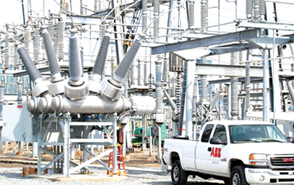
Figure 2.5 245 kV circuit breaker.
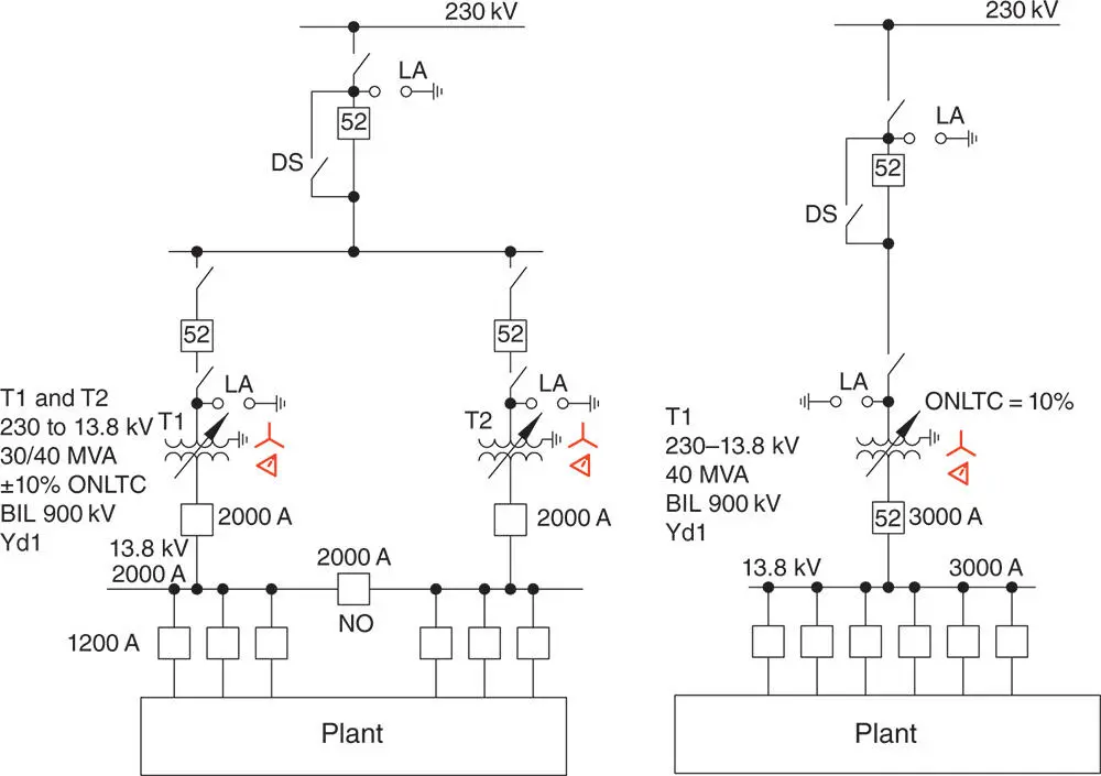
Figure 2.6 Double and single incomer diagram.
The transformers in our 30/40 MVA plant will be required to share the plant load, but each will also be capable of carrying the full load of the plant on their ONAF cooling in case one transformer fails.
Double power entry will be more reliable, though considerably more costly. A substation with two transformers, in addition to more HV switches will need three incoming HV circuit breakers to feed the two transformers. This substation will also require considerably more space.
For a smaller plant of up to 10 MVA, a single HV incomer may be considered acceptable as the cost of the HV breakers and two transformers might be excessive in comparison with the cost of the plant. In fact, a single incomer switching yard may include nothing more than a single H frame pole structure.
To support a smaller plant, several diesel generators (DGs) can be brought to site in trailers to temporarily replace a faulty transformer.
2.4.5 Utility Generating Capacity
This information we require to be able to determine if our plant will need some supplementary firm generation at site and also if we would be able to expand the plant in the future in case our ore body miraculously doubles up. We will look into a possibility of having a solar plant or a wind farm to augment our power sources. The solar and wind resources cannot be counted in as firm capacity, but simply as a source of power to displace the fuel consumption or import of power (see Chapters 25and 26).
2.4.6 Firm Capacity
This term is used in generation to determine the overall available MW capacity not considering one unit (single outage failure); therefore, a power plant with two units of 50 MW each has a firm capacity of one unit (50 MW). That is one generator unit out of two units, or two out of three units. Therefore, a firm capacity of a generating plant is the available generation MW capacity not counting one unit which is held as spare. Firm capacity of a transmission line is defined as one out of two circuits. A single circuit line has no firm capacity.
2.4.7 Line Protection
Utilities use specific protective relays and have definite strategies for the line protection: two to three zone distance, negative sequence, etc. The utility will likely ask us to match the protection relaying at our end to that of their end and to coordinate the settings between the two ends. The line protection will likely be by pilot differential relaying with fiber optic communications.
2.4.8 Lightning
We can look at the historic data of the lightning days/year in the area. The plant may be in a desert environment with a low isokeraunic level or in some mountainous region of high lightning intensity. Hopefully, we can obtain this data from the utility and design the switchyard and the overhead lines accordingly with appropriate overhead shielding, grounding, and lightning arrester protection (see Chapter 10for more details).
2.5 Main Plant Substation
Question? What is the difference between a switchyard and a substation? Is there a precise definition of one and the other? I have never heard one. In my circles, we called a facility with HV switches, circuit breakers, and transformers a substation. A switchyard was the same, but without transformers.
Читать дальшеИнтервал:
Закладка:
Похожие книги на «Practical Power Plant Engineering»
Представляем Вашему вниманию похожие книги на «Practical Power Plant Engineering» списком для выбора. Мы отобрали схожую по названию и смыслу литературу в надежде предоставить читателям больше вариантов отыскать новые, интересные, ещё непрочитанные произведения.


Обсуждение, отзывы о книге «Practical Power Plant Engineering» и просто собственные мнения читателей. Оставьте ваши комментарии, напишите, что Вы думаете о произведении, его смысле или главных героях. Укажите что конкретно понравилось, а что нет, и почему Вы так считаете.